Spark plug for internal combustion engine

a technology for internal combustion engines and spark plugs, which is applied to spark plugs, engine components, electrical appliances, etc., can solve the problems of increased mechanical wear of parts, and increased heat dissipation paths between the inner peripheral surface of the ground electrode, so as to shorten the heat dissipation paths and enhance the release of heat. , the effect of large contact area

Active Publication Date: 2017-03-16
DENSO CORP
View PDF0 Cites 4 Cited by
  • Summary
  • Abstract
  • Description
  • Claims
  • Application Information

AI Technical Summary

Benefits of technology

[0017]In the spark plug as described above, the outer diameter of the ground electrode is smaller than that of the front end surface of the small-diameter portion of the housing. The ground electrode is welded to the front end surface of the small-diameter portion of the housing. The ground electrode and the housing, therefore, face each other in contact with each other in an axial direction of the spark plug. Specifically, the ground electrode and the housing continuously and fully contact each other in the circumferential direction of the spark plug, thereby ensuring a large area of the contact and shortening a heat dissipating path between the inner peripheral surface of the ground electrode facing the spark gap and the housing. This enhances the release of heat from the ground electrode which is exposed to combustion of fuel in the engine and heated to high temperature to the housing mounted in an engine head, thus minimizing a rise in temperature of the ground electrode, thereby reducing mechanical wear of the inner peripheral surface of the ground electrode, which retards an increase in size of the spark gap to obtain a desired service life of the spark plug.
[0018]The ground electrode projects from the front end surface of the housing, so that the spark gap is located outside the front end of the housing in the axial direction of the spark plug, thereby avoiding contact of the flame, as created by a spark generated in the spark gap, with the housing, which usually causes the heat of the flame to be drawn into the housing, thus resulting in a failure in growing the flame. In other words, the cooling loss of thermal energy required to grow the flame is minimized to improve the ability of the spark plug to ignite the fuel.
[0019]The spark plug is designed to have the ground electrode which faces the outer peripheral surface of the center electrode and is welded to the front end surface of the small-diameter portion of the housing, thus facilitating the ease with which the ground electrode is positioned to the center electrode when they are welded together. Specifically, when the ground electrode is welded to the housing, it is possible to move the ground electrode along the front end surface of the small-diameter portion of the housing to fix a desired location of the ground electrode relative to the center electrode regardless of a variation in dimension of the parts of the spark plug, which facilitates the ease of adjustment of the spark gap between the center electrode and the ground electrode.
[0020]The housing has the vent holes formed therein, thus enhancing scavenging of the pocket that is, reducing the amount of residual gas accumulated in the pocket. This enhances the efficiency in scavenging the pocket during an exhaust stroke in the internal combustion engine and also facilitates suction of fresh air into the pocket, thereby enhancing the ability of the spark plug to ignite the fuel.
[0021]This disclosure, therefore, provides the spark plug and the production method of the spark plug which has an increased service life, an enhanced ability to ignite fuel, and a spark gap easy to adjust.

Problems solved by technology

The above spark plug, as described above, has the structure in which the ground electrode is tightly held inside the crimped front end of the housing to make a mechanical contact of the outer periphery of the ground electrode with the housing, thus resulting in an increased length of a heat dissipating path between the inner peripheral surface of the ground electrode which faces the spark gap and the housing.
This increases the risk of higher temperatures occurring in the ground electrode, which usually leads to an increase in mechanical wear of portions of the electrodes around the spark gap, thereby accelerating the rate at which the size of the spark gap increases, thereby shortening the time taken to reach an upper limit of a size of the spark gap.
It is, thus, difficult to produce spark plugs which have an increased service life.
The spark gap has an end located inside the front end of the housing in the lengthwise direction of the spark plug, thus encountering a probability that it is difficult for flame, as created by a spark generated in the spark gap, to grow, that is, a cooling loss increases in the spark plug, which will result in a reduced ability to ignite fuel in the engine.
It is, thus, difficulty to adjust the position of the ground electrode, that is, the size of the spark gap.
A variation in dimension or an assembling error of parts such as the housing etc. results in a failure in forming a desired spark gap even if the ground electrode is accurately positioned relative to the housing, thus requiring the need to position the ground electrode relative to the center electrode.
However, in the structure in which the ground electrode is disposed radially inside the crimped front end of the housing, a great variation in dimension or a great assembling error of parts of the spark plug will restrict movement of the ground electrode in a radial direction of the spark plug.
It is, thus, difficult to accurately adjust the size of the spark gap.
The ground electrode projects from the front end surface of the housing, so that the spark gap is located outside the front end of the housing in the axial direction of the spark plug, thereby avoiding contact of the flame, as created by a spark generated in the spark gap, with the housing, which usually causes the heat of the flame to be drawn into the housing, thus resulting in a failure in growing the flame.

Method used


Image

  • Spark plug for internal combustion engine
  • Spark plug for internal combustion engine
  • Spark plug for internal combustion engine

Examples


first embodiment

[0054]The spark plug 1 for use with an internal combustion engine and a production method thereof will be described below with reference to FIGS. 1 to 7.

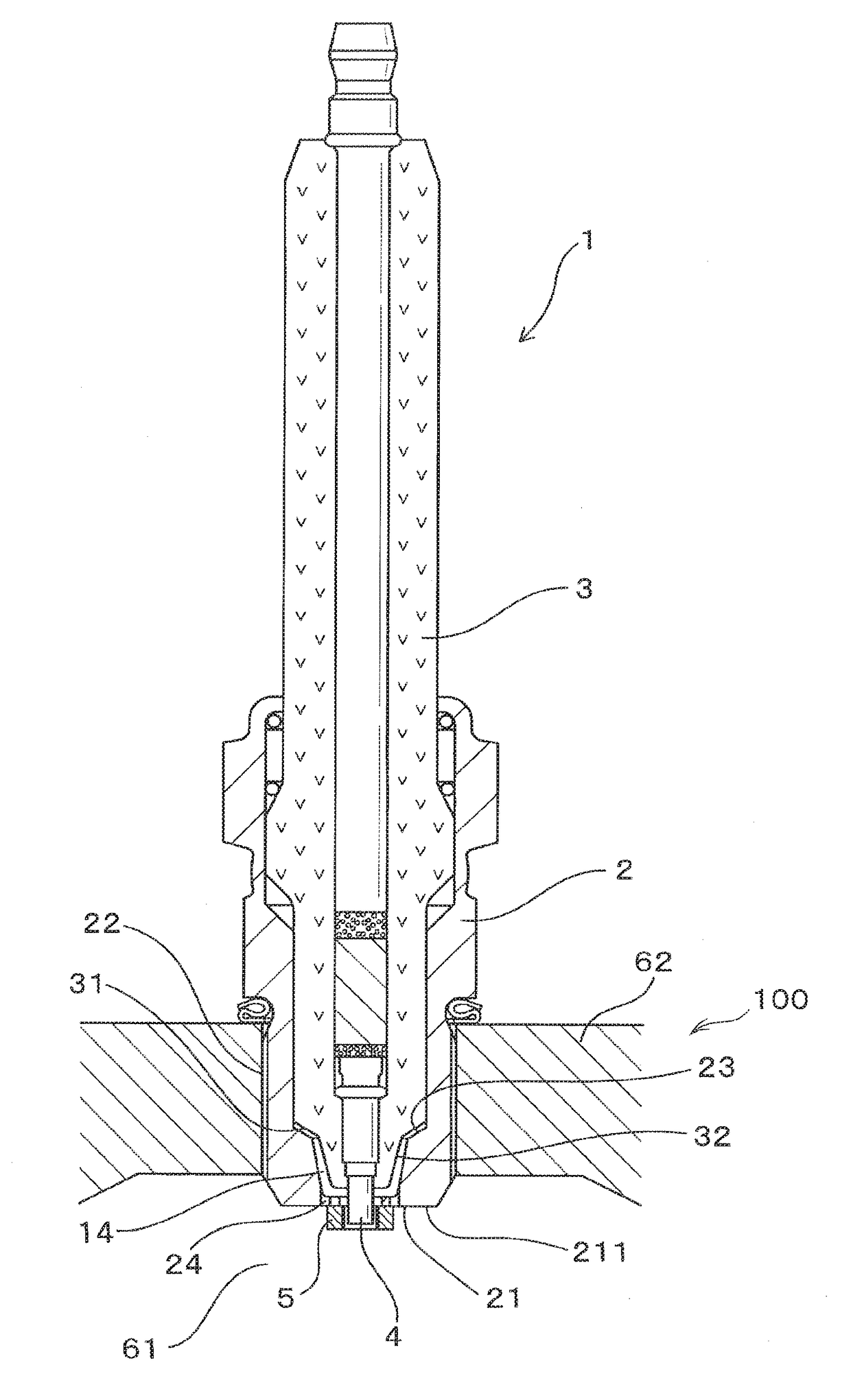
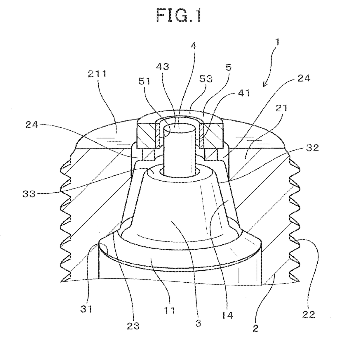
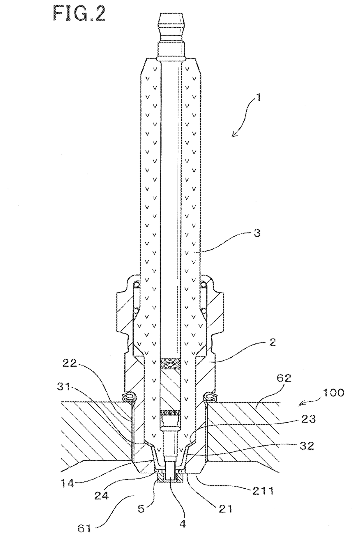
[0055]The spark plug 1 of the first embodiment, as illustrated in FIGS. 1 to 4, includes a hollow cylindrical housing 2 (also called a shell), a cylindrical porcelain insulator 3, a center electrode 4, and an annular ground electrode 5.

[0056]The housing 4 is installed in the internal combustion engine 100 with a front end (i.e., a head) thereof exposed to a combustion chamber 61 of the internal combustion engine 100. The porcelain insulator 3 is retained inside the housing 2. The center electrode 4 is retained inside the porcelain insulator 3 and partially projects from a front end of the porcelain insulator 3. The annular ground electrode 5 is secured to the front end of the housing 2.

[0057]The housing 2 has a small-diameter portion 21 formed on the front end of the housing 2. The small-diameter portion 21 has an inner diameter D4 ...

second embodiment

[0082]The spark plug 1 of this embodiment, as illustrated in FIGS. 8 to 10, has an annular weld 13 which welds the housing 2 and the ground electrode 5 together. The annular weld 13 is shaped to occupy a portion of a width of the ground electrode 5 which extends in the plug circumferential direction.

[0083]Specifically, the front end surface 211 of the small-diameter portion 21 faces a base end surface 52 of the ground electrode 5 through an annular boundary 12. The annular boundary 12 has an annular region which occupies a portion of a width thereof and fully extends in a circumferential direction thereof and in which the annular weld 13 is formed. The annular weld 13, as illustrated in FIG. 10, continuously extends in the circumferential direction of the annular boundary 12. The air vents 24 are, as can be seen in FIGS. 10 to 12, located outside the annular weld 13 in the plug radial direction.

[0084]The annular weld 13 has an inner circumferential edge 132 located outside the inner...

third embodiment

[0104]The spark plug 1 of this embodiment, as illustrated in FIGS. 15 and 16, have the vent holes 24 each of which is geometrically inclined at a given angle (except 0° and 90°) to the plug axial direction.

[0105]Specifically, each of the air vents 24, as can be seen in FIG. 16, extends upwardly and outwardly from the base end to the front end thereof. Each of the air vents 24, as clearly illustrated in FIG. 15, has the opening 241 which is fully located outside the outer circumference of the ground electrode 5. In other words, an inscribed circle which passes through outermost points of all the openings 241 is positioned outside the outer circumference of the ground electrode 5, as viewed in the plug axial direction.

[0106]Other arrangements are identical with those in the first embodiment.

[0107]The spark plug 1 of this embodiment is designed to have the air vents 24 with the openings 241 which are not closed by the ground electrode 5 at all, thus improving the ability of the spark p...


PUM


Abstract

A spark plug for an internal combustion engine is provided which includes a housing, a porcelain insulator, a center electrode, and an annular ground electrode. The housing has a small-diameter portion which has a smaller inner diameter and defines a front end thereof. The ground electrode is secured to a front end surface of the small-diameter portion and forms a spark gap between itself and an outer periphery of the center electrode. A pocket is formed between the inner periphery of the housing and a portion of the porcelain insulator which is located closer to a front end of the porcelain insulator than the mounting shoulder is. An air vent extends from outside the ground electrode in a radial direction of the spark plug to the pocket to establish communication between the pocket and the combustion chamber of the internal combustion engine.

Description

CROSS REFERENCE TO RELATED DOCUMENT[0001]The present application claims the benefit of priority of Japanese Patent Application No. 2015-182148 filed on Sep. 15, 2015, the disclosure of which is incorporated herein by reference.BACKGROUND[0002]1 Technical Field[0003]This disclosure relates generally to a spark plug for internal combustion engines which has an annular ground electrode disposed to face an outer circumference of a center electrode, and a production method thereof.[0004]2 Background Art[0005]For instance, Japanese Patent No. 5075127 discloses a spark plug for use in internal combustion engines mounted in automotive vehicles or cogeneration systems. The spark plug has an annular ground electrode which faces an outer periphery of a center electrode. The joint of the ground electrode to a housing of the spark plug is achieved by crimping a front end of the housing inwardly to define a spark gap between the outer circumference of the center electrode and the inner circumfere...

Claims


Application Information

Patent Timeline
Patent Type & Authority Applications(United States)
IPC IPC(8): H01T13/16F02P15/00H01T13/38
CPCH01T13/16F02P15/00H01T13/38H01T13/14H01T13/32H01T13/00
Inventor DEGUCHI, MASATAKASHIBATA, MASAMICHITERADA, KANECHIYOMIWA, TETSUYAOSAMURA, HIRONORITSUKAMOTO, YUUKI
Owner DENSO CORP
Why Eureka
Try Eureka