Pressure Sensor System

a sensor system and pressure sensor technology, applied in the direction of fluid pressure measurement, instruments, basic electric elements, etc., can solve the problems of system complexity, plastic or metal housings that are only usable in aggressive media to a limited extent, and plastic or metal housings additionally incompatible with alternative joining technologies, etc., to achieve the effect of improving media resistan

Active Publication Date: 2017-03-30
EPCOS AG
View PDF10 Cites 3 Cited by
  • Summary
  • Abstract
  • Description
  • Claims
  • Application Information

AI Technical Summary

Benefits of technology

[0017]By way of a suitable selection of the ceramic material of the housing body having a coefficient of thermal expansion which is in the range of the material of the pressure sensor chip, i.e., for example, silicon, thermally-induced mechanical tensions, which can result in corruption of the pressure sensor signal, may advantageously be strongly reduced or even prevented entirely.
[0018]According to a further embodiment, the ceramic material comprises mullite, i.e., aluminum silicate. Furthermore, it can also be possible that the ceramic material of the housing body comprises aluminum oxide, zirconium oxide, aluminum nitride, silicon carbide, or silicon nitride. The ceramic housing body can also comprise a combination of the mentioned materials. Furthermore, the ceramic housing body can also consist of one or more of the mentioned ceramic materials. The advantage of the pressure sensor system described here is the monolithic embodiment of the housing body using a suitable ceramic material such as those mentioned above. A substantially improved media resistance is thus achievable in comparison to the prior art.

Problems solved by technology

Sensor systems having plastic or metal housings are only usable in aggressive media to a limited extent because of corrosion occurrences.
Plastic housings are additionally incompatible with alternative joining technologies, for example, welds and soldered connections.
Therefore, most sensor systems in the prior art consist of material combinations, which in turn require additional connections and make the systems very complex.

Method used


Image

  • Pressure Sensor System
  • Pressure Sensor System
  • Pressure Sensor System

Examples


Embodiment Construction

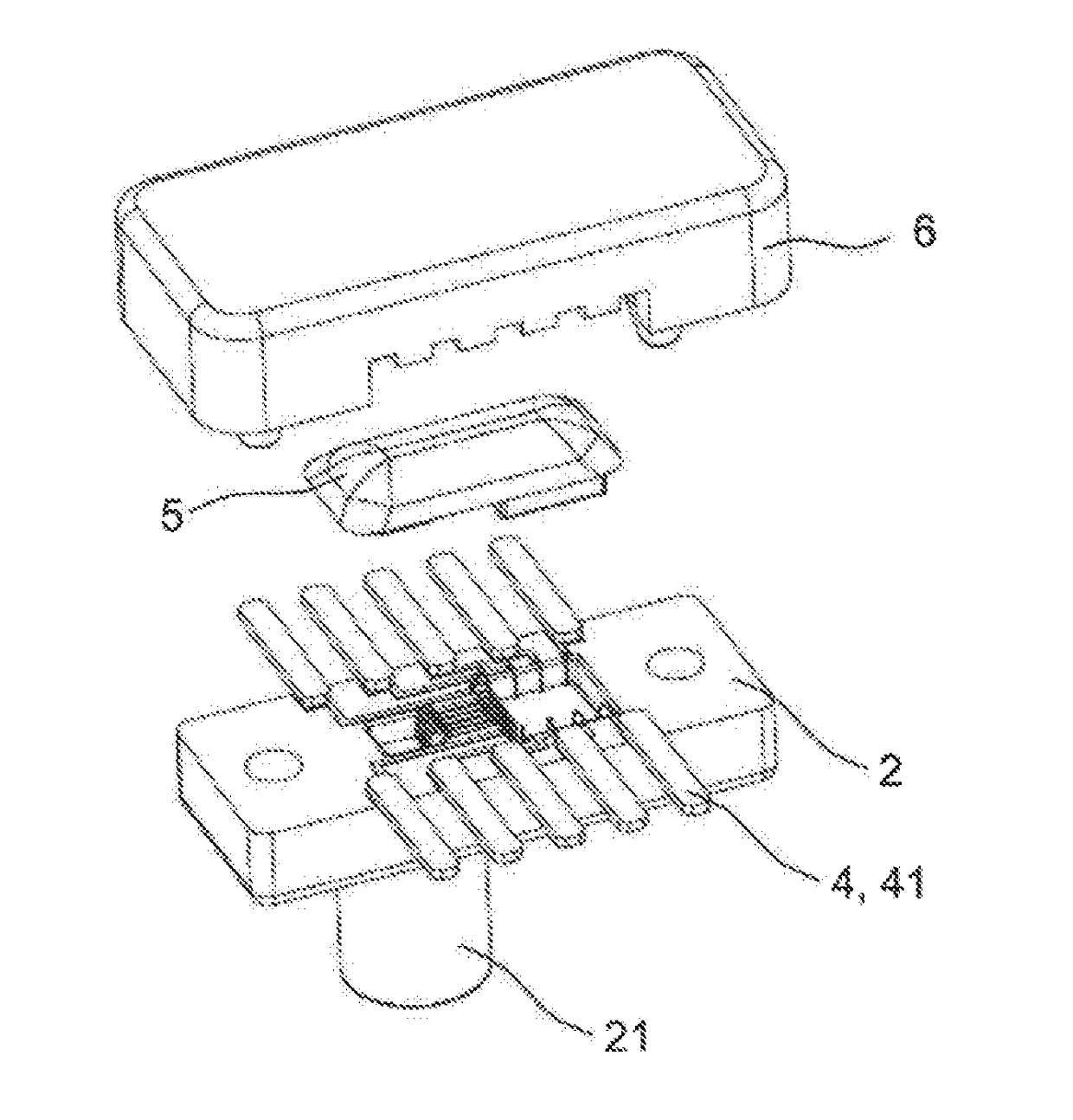
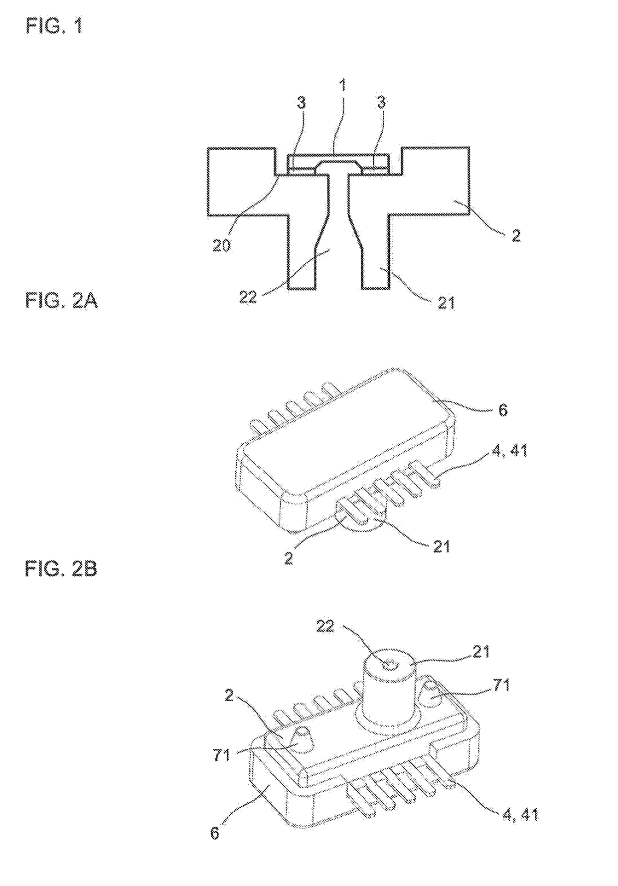
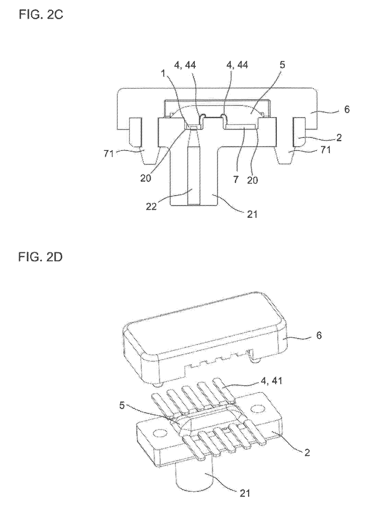
[0049]FIG. 1 shows a pressure sensor system according to one exemplary embodiment, which comprises a pressure sensor chip 1, which is mounted on a mounting receptacle 20 of a ceramic housing body 2. The mounting receptacle 20 is formed by a depression of the housing body 2 on a mounting side of the housing body 2. Alternatively thereto, the mounting receptacle 20 can also be formed as a protrusion instead of a depression, for example.

[0050]Furthermore, the housing body 2 has a pressure feed 22, via which the pressure to be measured can be fed to the pressure sensor chip 1. The pressure feed 22 extends for this purpose up to the mounting receptacle 20. To connect the pressure sensor system, a pressure fitting 21 can be provided, as shown in FIG. 1, which can be formed as cylindrical or conical and can comprise, for example, a thread, a part of a bayonet socket, or teeth.

[0051]The mounting of the pressure sensor chip 1 on the mounting receptacle 20 of the ceramic housing body 2 and th...


PUM

PropertyMeasurementUnit
temperatureaaaaaaaaaa

Abstract

A pressure sensor system having a pressure sensor chip is specified. The pressure sensor chip is mounted on a mounting receptacle of a ceramic housing body having a pressure feed guided to the pressure sensor chip. The housing body is three-dimensionally shaped and monolithically formed and is formed by a ceramic material having a coefficient of thermal expansion which deviates by less than 30% from the coefficient of thermal expansion of the pressure sensor chip in a temperature range of greater than or equal to −40° C. and less than or equal to 150° C.

Description

CROSS-REFERENCE TO RELATED APPLICATIONS[0001]This patent application is a continuation application of U.S. patent application Ser. No. 14 / 767,044, filed Aug. 11, 2015, which is a national phase filing under section 371 of PCT / EP2014 / 051031, filed Jan. 20, 2014, which claims the priority of German patent application 10 2013 101 731.2, filed Feb. 21, 2013, each of which is incorporated herein by reference in its entirety.TECHNICAL FIELD[0002]A pressure sensor system having a pressure sensor chip is specified.BACKGROUND[0003]Continuously rising demands on pressure sensors with respect to the long-term resistance in aggressive media, the usage temperatures, and the robustness require particularly resistant sensor systems, if possible in conjunction with integrated sensor signal processing. It is simultaneously required that such systems be producible by cost-effective manufacturing and have reduced system complexity.[0004]For easy mounting in an application, sufficient mechanical stabil...

Claims


Application Information

Patent Timeline
Patent Type & Authority Applications(United States)
IPC IPC(8): G01L19/14C04B35/626G01L19/04C04B35/185G01L19/06G01L19/00
CPCG01L19/141G01L19/0681G01L19/0627G01L19/0038G01L19/0084C04B2235/656C04B35/185C04B35/626C04B2235/3463C04B2235/6022G01L19/04G01L19/143H01L2224/48091H01L2924/00014C04B35/64
Inventor IHLE, JANPESCHKA, ANDREASHUNDERTMARK, BERTBOHL, BENJAMINOSTRICK, BERNHARD
Owner EPCOS AG
Why Eureka
Try Eureka