Laser soldering process

a laser soldering and process technology, applied in the direction of laser beam welding apparatus, soldering apparatus, etc., can solve the problems of adversely affecting quality, laser soldering has technical complications, and cannot meet the technical requirements of certain applications for soldering

Inactive Publication Date: 2017-04-13
TE CONNECTIVITY CORP
View PDF4 Cites 6 Cited by
  • Summary
  • Abstract
  • Description
  • Claims
  • Application Information

AI Technical Summary

Benefits of technology

[0005]In an embodiment, a laser soldering process includes beaming a lower-intensity laser beam from a laser soldering system at a first position, analyzing infrared feedback of the lower-intensity laser beam at the first position, and beaming a higher-intensity laser beam at a second position, the second position corresponding with the infrared feedback of the lower-intensity laser beam. The lower-intensity laser beam generates a lower temperature below a soldering temperature of a solder material and the higher-intensity laser beam generates a higher temperature above the soldering temperature.
[0006]In another embodiment, a laser soldering process includes beaming a lower-intensity laser beam from a laser soldering system at a first position, then analyzing infrared feedback of the lower-intensity laser beam at the first position using an infrared and visible light sensing camera, then repositioning one or more of the laser soldering system, a first conductive member coated with a solder material to be soldered, and a second conductive member coated with the solder material, and then beaming a higher-intensity laser beam from the laser soldering system to one or both of the first conductive member and the second conductive m

Problems solved by technology

However, many individuals skilled in the art believe that lasers are incapable of achieving the technical requirements for soldering in certain applications.
Laser soldering has technical complications.
Although there are beneficial aspects of being devoid of

Method used


Image

  • Laser soldering process
  • Laser soldering process

Examples


Embodiment Construction

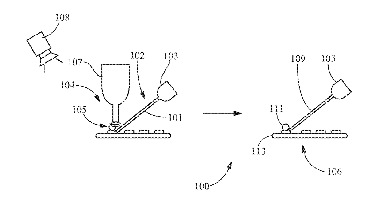
[0012]Provided are laser soldering processes. Embodiments of the present disclosure, for example, in comparison to concepts failing to include one or more of the features disclosed herein may provide one or more of the following benefits, including, but not limited to: i) use of lasers for precise (for example, having tightly-controlled temperatures) and high-quality soldering on materials having dimensions (for example, size, pitch, and / or thickness) as small as 0.05 millimeters; ii) reduce or eliminate uneven heating previously believed to be a feature of laser soldering; iii) reduce or eliminate unintended burning of solder; iv) reduce or eliminate thermal damage to heat-sensitive components during manufacturing (for example, of components that receive thermal damage when exposed to temperatures of greater than 343° C.); v) reduce or eliminate vertical overhang defects in solder joints; vi) allow for more precise soldering; vii) allow laser soldering operation which are devoid of...


PUM

PropertyMeasurementUnit
Thicknessaaaaaaaaaa
Thicknessaaaaaaaaaa
Lengthaaaaaaaaaa

Abstract

Laser soldering processes are disclosed. The laser soldering process includes beaming a lower-intensity laser beam from a laser soldering system at a first position, analyzing infrared feedback of the lower-intensity laser beam at the first position, and beaming a higher-intensity laser beam at a second position, the second position corresponding with the infrared feedback of the lower-intensity laser beam. The lower-intensity laser beam generates a lower temperature below a soldering temperature of a solder material and the higher-intensity laser beam generates a higher temperature above the soldering temperature.

Description

FIELD OF THE INVENTION[0001]The present invention is directed to manufacturing and industrial processes. More particularly, the present invention is directed to laser soldering processes.BACKGROUND OF THE INVENTION[0002]Commercial use of lasers for soldering has been tried in the past. However, many individuals skilled in the art believe that lasers are incapable of achieving the technical requirements for soldering in certain applications. For example, prior attempts to use laser soldering have been on the scale of soldering materials used in components, such as, wires, conductors, and strands having diameters or cross section widths of at least 0.5 millimeters and termination base components, such as copper traces or pads in printed circuit boards having widths of at least 0.5 millimeters and thicknesses of 0.5 millimeters.[0003]Laser soldering has technical complications. Laser soldering does not involve physical contact. Although there are beneficial aspects of being devoid of p...

Claims


Application Information

Patent Timeline
IPC IPC(8): B23K1/005B23K26/06B23K26/32
CPCB23K1/0056B23K26/06B23K26/32B23K1/19B23K26/034
Inventor WU, HUADONGBOLHA, SARA ELIZABETHELDEEB, YASSER M.
Owner TE CONNECTIVITY CORP
Why Eureka
Try Eureka