Hybrid laser countermeasure line replaceable unit and method of upgrading therewith

a laser countermeasure and laser technology, applied in direction controllers, instruments, weapons, etc., can solve the problems of limited defensive capabilities of legacy countermeasure laser systems, high cost of developing completely new countermeasure systems, and inability to meet the needs of new countermeasure systems

Active Publication Date: 2017-04-13
BAE SYST INFORMATION & ELECTRONICS SYST INTERGRATION INC
View PDF9 Cites 7 Cited by
  • Summary
  • Abstract
  • Description
  • Claims
  • Application Information

AI Technical Summary

Benefits of technology

[0009]In another embodiment, one aspect of the present disclosure may provide a hybrid laser countermeasure line replaceable unit including: a housing defining one or multiple internal cavities and a laser beam first exit aperture and a laser beam second exit aperture; a first transparent lens at the laser beam first exit aperture enabling passage of electromagnetic radiation therethrough; a second transparent lens at the laser beam second exit aperture enabling passage of electromagnetic radiation therethrough; a first laser beam ge

Problems solved by technology

These legacy countermeasure laser systems are limited in their defensive capabilities.
Issues continue to exist with the devices that produce and carry the two types of lasers (i.e., pulsed and CW las

Method used


Image

  • Hybrid laser countermeasure line replaceable unit and method of upgrading therewith
  • Hybrid laser countermeasure line replaceable unit and method of upgrading therewith
  • Hybrid laser countermeasure line replaceable unit and method of upgrading therewith

Examples


first embodiment

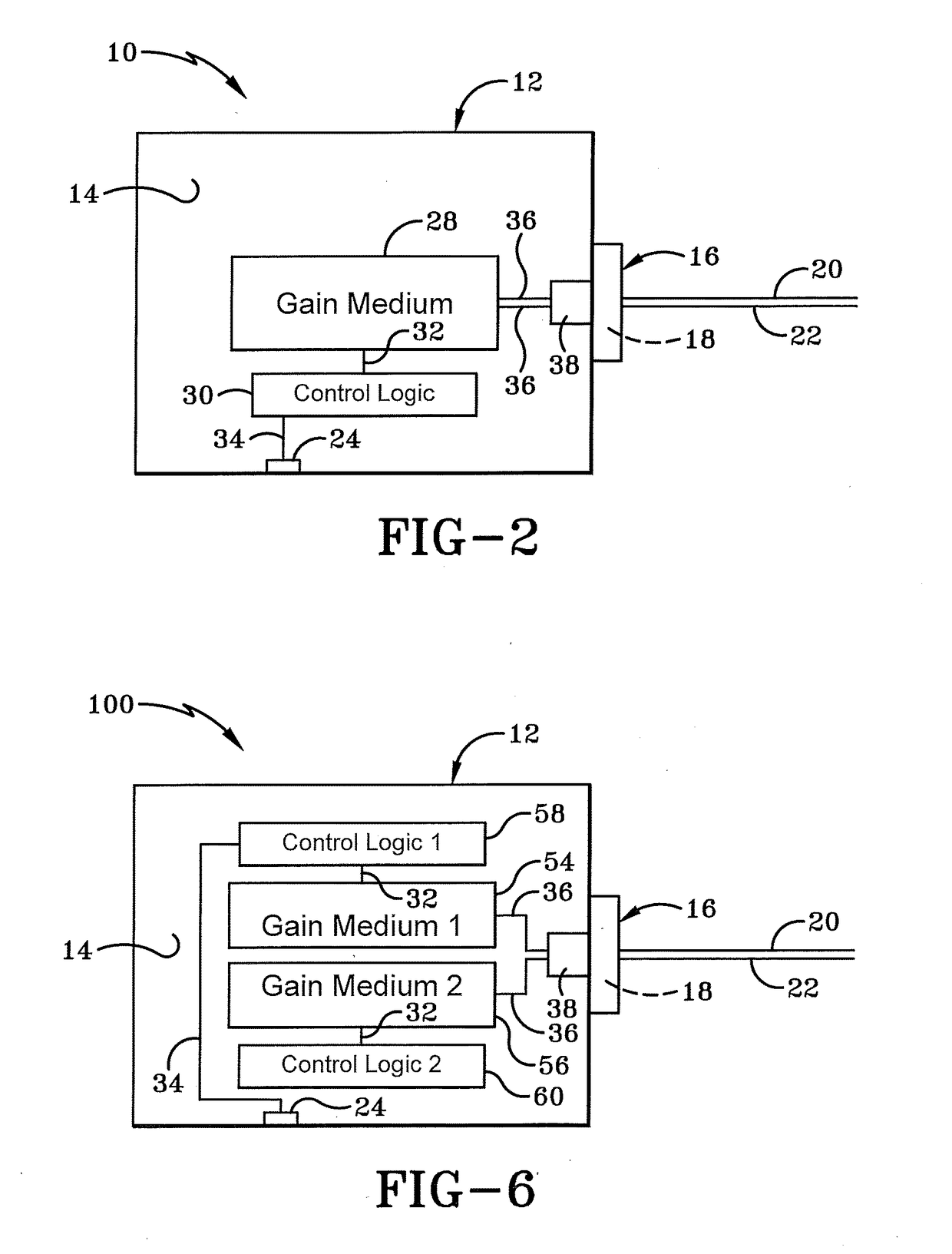
[0037]As depicted in FIG. 2, hybrid laser line replaceable unit 10 includes a single gain medium 28 carried by housing 12 within internal cavity 14. Gain medium 28 may be operatively connected to a power source through a power input 26. Control logic 30 is operatively coupled to gain medium 28 via transmission line 32. The modulation control inlet 24 is connected to control logic 30 via transmission line 34. A laser output 36 may directly exit single gain medium 28 and travel freely or through a transmission line, both of which are represented by reference numeral 36 to combining logic 38.

[0038]First laser beam 20 is generated in gain medium 28 within internal cavity 14 and travels along output 36 through combining logic 38 and through laser beam exit aperture 16 and lens 18. In one particular embodiment, the first laser beam 20 is a pulsed laser beam receiving modulation signals from a legacy modulation source 40 to pulse first laser beam 20 as one having ordinary skill in the art ...

second embodiment

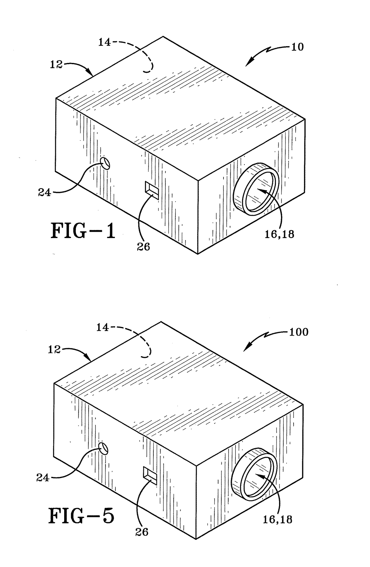
[0042]As depicted in FIG. 5 and FIG. 6, a hybrid laser countermeasure line replaceable unit 100 includes a first gain medium 54 and a second gain medium 56, both carried by housing 12 inside internal cavity 14. A first control logic 58 is operatively coupled with first gain medium 54. A second control logic 60 is operatively coupled to second gain medium 56. Second control logic is coupled with modulation source 40 through inlet 24 and transmission line 34.

[0043]First control logic 58 is operatively coupled to first gain medium 54. As will be described in greater detail below, transmission line 34 transmits a modulated signal from modulation source 40 through control logic 58 into gain medium 54 to create a first laser beam 20 that is a pulsed laser beam. Second control logic 60 is operatively coupled to second gain medium 56 to control second laser beam 22 which is a continuous wave laser beam.

[0044]As depicted in FIG. 7A, first laser beam 20 may be generated from the first gain me...


PUM


Abstract

A hybrid laser countermeasure line replaceable unit and method of upgrading therewith is provided. The unit includes two generable laser beams, namely, a first pulsed laser beam and a second continuous wave laser beam. Further embodiments may have multiple pulsed and continuous wave laser beams as necessary. The two beams in this single unit either may be generated from a single gain medium or may be generated from multiple gain mediums inside the line replaceable unit. The two beams may be combined if necessary to provide greater likelihood of success as a countermeasure to defend against optically guided incoming threats to a vehicle, such as military aircraft.

Description

BACKGROUND[0001]Technical Field[0002]The present disclosure relates to generally electronic countermeasures on vehicles. More particularly, the present disclosure relates to electronic countermeasures utilizing lasers. Specifically, the present disclosure relates to device having at least one pulsed laser and at least one continuous wave laser generated from a single line replaceable unit and a method of upgrading legacy single laser systems with a hybrid laser system for greater countermeasure defenses.[0003]Background Information[0004]Historically, there have been two types of lasers used for electro-optical (EO) infrared (IR) systems for military applications. The first type are pulsed lasers which are used for applications like ranging, LIDAR, designation, and missile countering. The second type are Continuous Wave (CW) lasers which have been used for illumination, missile countering, and targeting. As the requirements for additional capabilities and functionality are developed,...

Claims


Application Information

Patent Timeline
IPC IPC(8): F41G7/22G01S7/495G01S7/481F41H13/00
CPCF41G7/224G01S7/4815G01S7/495F41H13/0056
Inventor RADL, ANDREW J.YOUNG, YORK E.
Owner BAE SYST INFORMATION & ELECTRONICS SYST INTERGRATION INC
Why Eureka
Try Eureka