Electric vehicle and vehicle power feeding method

a technology for electric vehicles and vehicles, applied in the direction of electric devices, power rails, propulsion by batteries/cells, etc., can solve the problem of long charging time and achieve the effects of reliable charging, reduced infrastructure investment costs, and lightening or alleviating damage to the contact site of the energizing portion with respect to the power supply portion

Active Publication Date: 2017-04-20
HONDA MOTOR CO LTD
View PDF13 Cites 7 Cited by
  • Summary
  • Abstract
  • Description
  • Claims
  • Application Information

AI Technical Summary

Benefits of technology

[0014]According to the present invention, when the energizing portion contacts the power supplying portion. the first charging control is carried out in which the input current to the energy storage device (including an amount of charge per unit time thereof) is treated as the control object. Owing thereto, an instantaneous surge current at the time that energizing is started can be prevented, and welding or fusion between the power supplying portion and the energizing portion, or damage to the electrical circuitry on the side of the power supplying portion or on the side of the energizing portion can be prevented. Further, after the first charging control, the second charging control, which implements supply of power without voltage conversion or implements supply of power using the target electrical power (more specifically, supply of power in which the input current and the input voltage to the energy storage device are not directly limited), is carried out for a longer time period than that of the first charging control. Accordingly, charging over a very short time is enabled by a combination of the first charging control and the second charging control.
[0020]The electric vehicle may comprise an aim displacement mechanism that causes the energizing portion to project out laterally of a vehicle body during traveling. Owing thereto, since it is possible for the power supplying portion to be disposed laterally of the travel path, installation of the power supplying portion can be performed at low cost. More specifically, compared to a case in which the power supplying portion is arranged upwardly of the vehicle body, since it is possible to dispose the power supplying portion at a lower position, it is possible to simplify equipment for supporting the power supplying portion. Further, although it is necessary to embed the power supplying portion in the travel path in the case that the power supplying portion is arranged below the vehicle body, in the case that the power supplying portion is arranged to the side of the travel path, there is no need to embed the power supplying portion in the travel path. Therefore, it is possible for the power supplying portion to be arranged with ease.

Problems solved by technology

Therefore, the charging time is still long, and responsive thereto, since the aerial line section must also be long, problems have occurred in putting this technique into practice.

Method used


Image

  • Electric vehicle and vehicle power feeding method
  • Electric vehicle and vehicle power feeding method
  • Electric vehicle and vehicle power feeding method

Examples


embodiment

I. Embodiment

1A. Configuration

[1A-1. Overall Configuration]

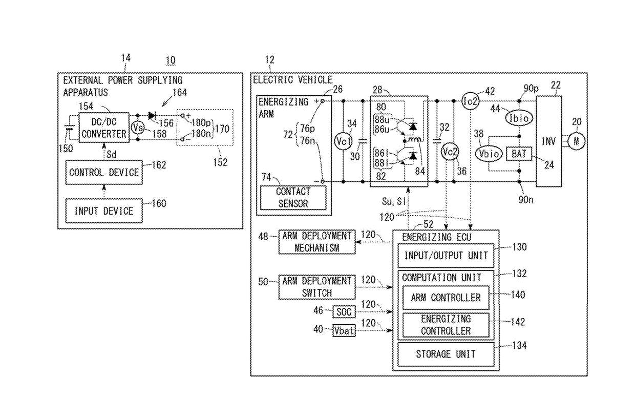
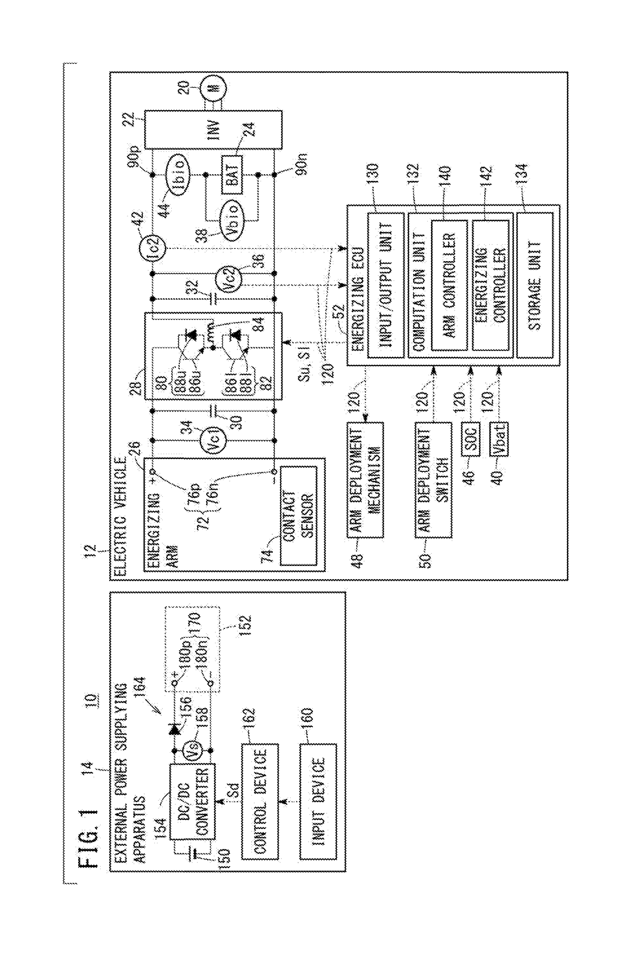
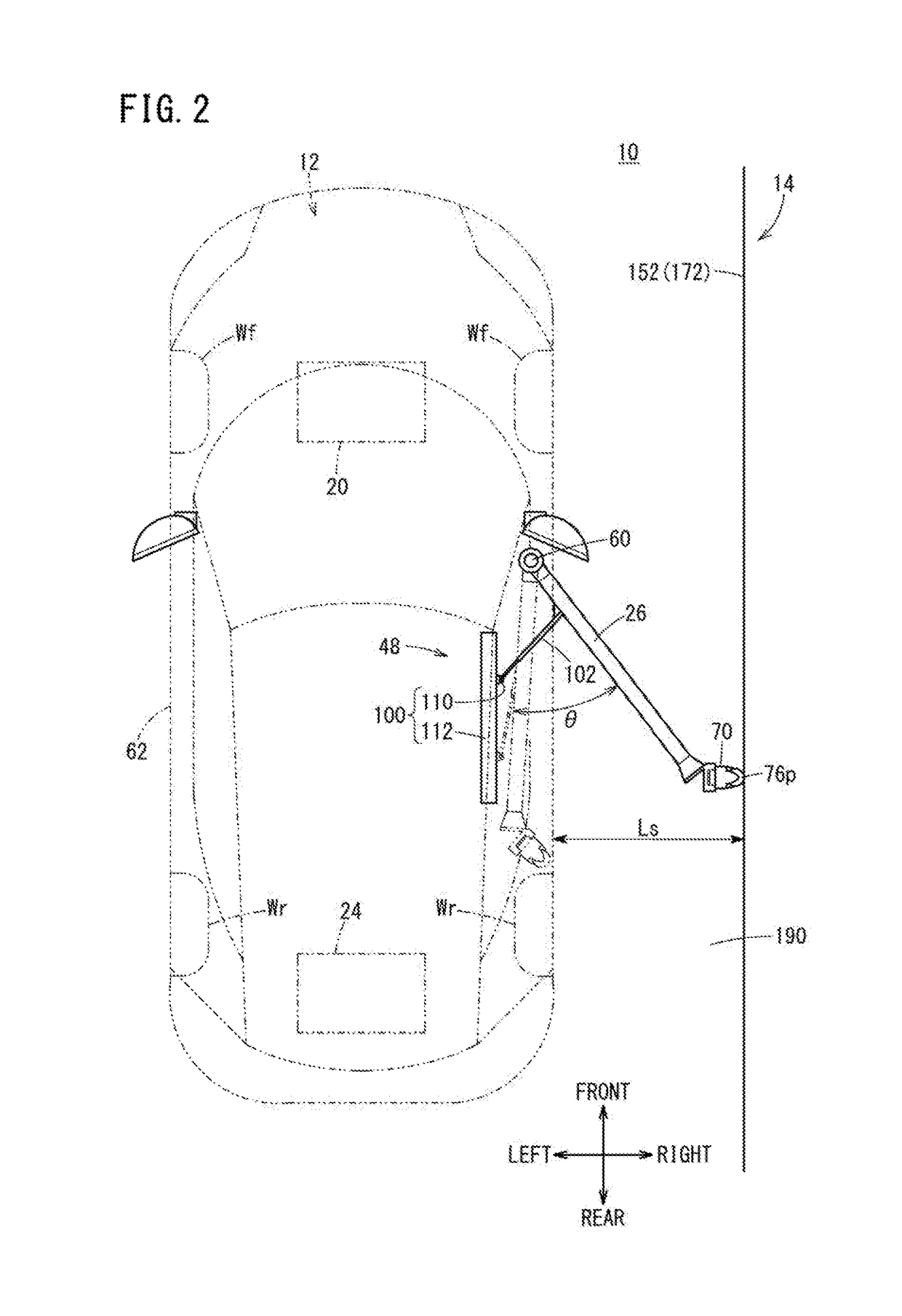
[0033]FIG. 1 is an outline schematic view of a charging system 10 equipped with an electric vehicle 12 according to act embodiment of the present invention. FIG. 2 is a plan view showing with emphasis portions of the charging system 10. FIG. 3 is a front view showing with emphasis portions of the charging system 10. As shown in FIGS. 1 through 3, the charging system 10, in addition to the electric vehicle 12 (hereinafter also referred to as a “vehicle 12”), includes an external power supplying apparatus 14 (hereinafter also referred to as a “power supplying apparatus 14”). Any of the directions (“front”, “rear”, “left”, “right”, “up”, “down”) in FIGS. 2 and 3 are directions on the basis of the vehicle 12 (the same holds true for FIG. 4).

[0034]According to the present embodiment, electrical power is supplied to the vehicle 12 from the power supplying apparatus 14, and charging of a battery 24 (see FIG. 1) for traveling of the...


PUM


Abstract

Provided are an electric vehicle and a vehicle power feeding method capable of charging, at an ultra-high speed, an electricity storage device of the electric vehicle that travels on a trackless road. A control device of the electric vehicle executes a first charging control for controlling a voltage converter to limit the input current from a power feeding portion to an electricity storage device or the variation of the input current per unit time and allowing the voltage converter to charge the electricity storage device; and a second charging control for, for example, slopping the transforming operation of the voltage converter and allowing the voltage converter to charge the electricity storage device. Both charging controls are executed while moving the contact point between an electrical connection portion and the power feeding portion, and the execution time of the second charging control is longer than that of die first charging control.

Description

TECHNICAL FIELD[0001]The present invention relates to an electric vehicle that travels on a trackless trajectory and a vehicle power supplying (feeding) method in which the electric vehicle is used. More specifically, the present invention relates to an electric vehicle and a vehicle power supplying method in which the electric vehicle is used, which are capable of supplying power at ultra-high-speed by bringing an energizing arm into contact with external power lines during traveling.BACKGROUND ART[0002]Heretofore, as charging methods for an electric vehicle, there have been known contact type charging for charging an electric vehicle by having a charging nozzle connect to the electric vehicle while the electric vehicle is stopped, and non-contact charging for charging the electric vehicle through magnetic forces in a non-contact state.[0003]In the former method, even in the case of a comparatively fast rapid charging system, with currently installed charging devices, time on the o...

Claims


Application Information

Patent Timeline
Patent Type & Authority Applications(United States)
IPC IPC(8): B60L11/18H02J7/00
CPCB60L11/1811B60L11/1803B60L11/1816B60L11/1825B60L11/185B60L11/1827B60L2240/54H02J7/0045B60L2210/44B60L2210/30B60L2220/10B60L2230/10B60L2240/12H02J7/0027B60L5/36B60M1/30Y02T10/7072Y02T90/14B60L2210/14B60L2270/20B60L50/51B60L53/20B60L53/35B60L53/11B60L53/16H02J7/007Y02T10/70Y02T10/72Y02T90/12H02J3/322H02J2310/48
Inventor TAJIMA, TAKAMITSU
Owner HONDA MOTOR CO LTD
Why Eureka
Try Eureka