
Spreader for spreading granular material and method of spreading granular material

a technology of granular material and spreader, which is applied in the direction of loading/unloading, packaging, construction, etc., can solve the problems of long down time for repairs, very different repose angles of materials used to combat ice and/or snow, and high initial cost and upkeep costs

Active Publication Date: 2017-04-20
SNO WAY INT
View PDF7 Cites 14 Cited by
  • Summary
  • Abstract
  • Description
  • Claims
  • Application Information

AI Technical Summary

Benefits of technology

This patent is about new and better spreaders for spreading granular products. One version is a hopper spreader, which has a hopper for storing the granular material and a spreading unit that spreads it. The invention provides improvements for handling both easy-flow and difficult-flow materials. The hopper spreader apparatus includes a conveying unit and a rotating roll that controls the flow of granular material from the hopper to the spreading unit. This allows for better control of high-flow and low-flow materials, ensuring even distribution. Overall, the invention enables better and more efficient spreading of granular materials.

Problems solved by technology

Unfortunately, the materials used to combat ice and / or snow as outlined above have very different angles of repose.
One of the problems of the existing art is that there are two primary categories of spreaders, the drag chain spreader and the auger spreader.
The drag chain spreader can flow a wide range of materials, however it is expensive in initial cost and upkeep.
Repairs are extensive requiring prolonged down time for repairs.
Additionally, the spread quality of the drag chain spreader is not optimum and as a result too much material is consumed which is wasteful and expensive.
This in turn requires the end user to change settings, such as on an inverted-v that is positioned above the auger to prevent jamming, on the auger spreader and in some cases may end up causing the auger to jam up.
If this is not set correctly, the end user if not careful can end up with a hopper full of material that will not dispense.
Bagged salts on the other hand, which are high flow materials and easy to dispense, are more expensive and require special storage requirements.
This is especially problematic for users who are concerned about even coverage and effective material distribution for either grip or melting efficacy.
A second method which is used with success requires high horsepower, expensive gearing, large auger flighting, robust auger shafting, vibrators, and in some cases inverted-v's, is the auger system.
Matching the auger flighting so that the material is dispensed at proper rates can become a complex problem, requiring baffle adjustment, rpm adjustment, and vibrator impulses.
Further, due to the large size and slow speed the large auger system can exhibit pulsing effects when moving the large slug of flow resistant material.
The problem with both systems is flowing high flow material, e.g. those that readily flow on their own and have an angle of repose of less than 40 degrees.
Very often the auger will become overwhelmed in the high flow materials.
Unfortunately, they are stuck with poor spread quality, excessive flow quantity and road-transport-spillage especially when using high flow materials.
A further problem experienced by current spreaders is that the emptying profile for both drag chain spreaders and auger spreaders causes an uneven weight distribution during spreader use.
When the spreader is located in the bed of a vehicle, this translates into vehicle handling problems where the weight gradually shifts toward the rear of the vehicle which can cause the front steering to become less tractable.
As such, there is not a single system that currently handles materials that flow easily and that are flow resistant as well as provides a more uniform emptying profile.

Method used


Image

  • Spreader for spreading granular material and method of spreading granular material
  • Spreader for spreading granular material and method of spreading granular material
  • Spreader for spreading granular material and method of spreading granular material

Examples


Embodiment Construction

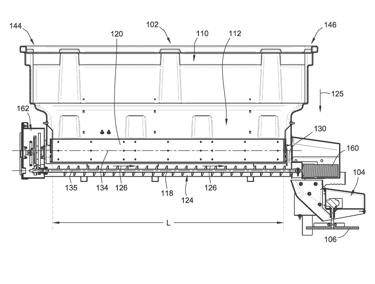
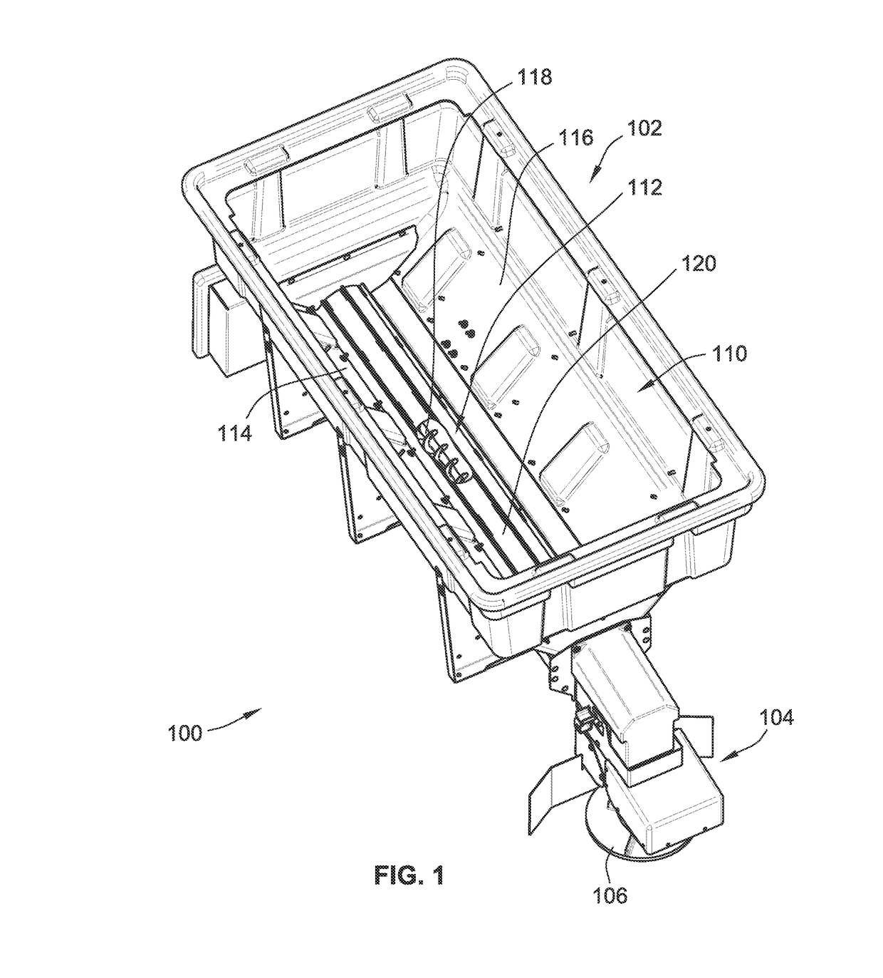
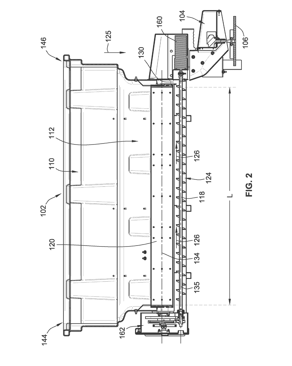
[0072]FIG. 1 illustrates a hopper spreader apparatus 100 in accordance with an embodiment of the present invention. The hopper spreader apparatus is designed to distribute granular material including easily flowing material and flow resistant material such as, for example, sand (including dry and wetted sand), salt, salt with a liquid additive, or a mixture of sand and salt. While the hopper spreader apparatus 100 finds particular use in spreading sand and / or salt for cold weather applications, the hopper spreader apparatus 100 can be used for distributing other materials in other situations, such as for example, fertilizer.

[0073]The hopper spreader apparatus 100 generally includes a hopper 102 for storing the material to be distributed and a spreading unit 104 for spreading the material. In the illustrated embodiment, the spreading unit 104 is in the form of a spinner assembly that includes a rotating spinner 106 that spreads the material by centrifugally propelling the material th...


PUM


Abstract

In one embodiment, a hopper spreader apparatus for spreading granular material is provided. The hopper spreader apparatus includes a hopper, a spreading unit, and a dispensing unit. The hopper has a storage cavity for storing the granular material to be spread. The spreading unit spreads the granular material. The dispensing system transports the granular material from the hopper to the spreading unit. The dispensing system includes a conveying unit and a rotating first roll. The conveying unit conveys the granular material toward the spreading unit. The rotating first roll controls a flow of granular material from the hopper to the conveying unit. The use of the rotating roll allows for control of high flow material (such as for example dry salt) while allowing for improved collapse and break-up of low flow material (such as for example wetted sand).

Description

FIELD OF THE INVENTION[0001]This invention generally relates to spreader apparatuses for spreading granular material and methods of spreading granular materialBACKGROUND OF THE INVENTION[0002]When the snow falls and has been cleared to a thin layer, or it rains and starts to freeze, it is desirable to make a safe tractive surface to walk and drive on in parking lots, driveways and even walk ways. The prime method for making traction is to either melt the snow and / or ice, such as using salt, to expose a tractive surface below or spread a material tractive material, such as sand, to increase the traction on the slippery surface. The tractive action of the sand on the surface of the ice gives an immediate tractive surface. Further, a combination of salt and sand can be used where the salt acts to penetrate through the snow-ice barrier and eventually melt away the majority of the snow-ice and allow the tractive surface (i.e. the pavement or a gravel road) to be exposed while the sand pr...

Claims


Application Information

Patent Timeline
Patent Type & Authority Applications(United States)
IPC IPC(8): E01H10/00B65G31/04B65G33/10B65G11/02B65G11/20
CPCE01H10/007B65G11/026B65G2201/045B65G33/10B65G31/04B65G11/20B65G65/46B65G65/4881A01C15/16
Inventor GAMBLE, II, ROBERT N.WENDORFF, TERRY C.
Owner SNO WAY INT
Learn More