
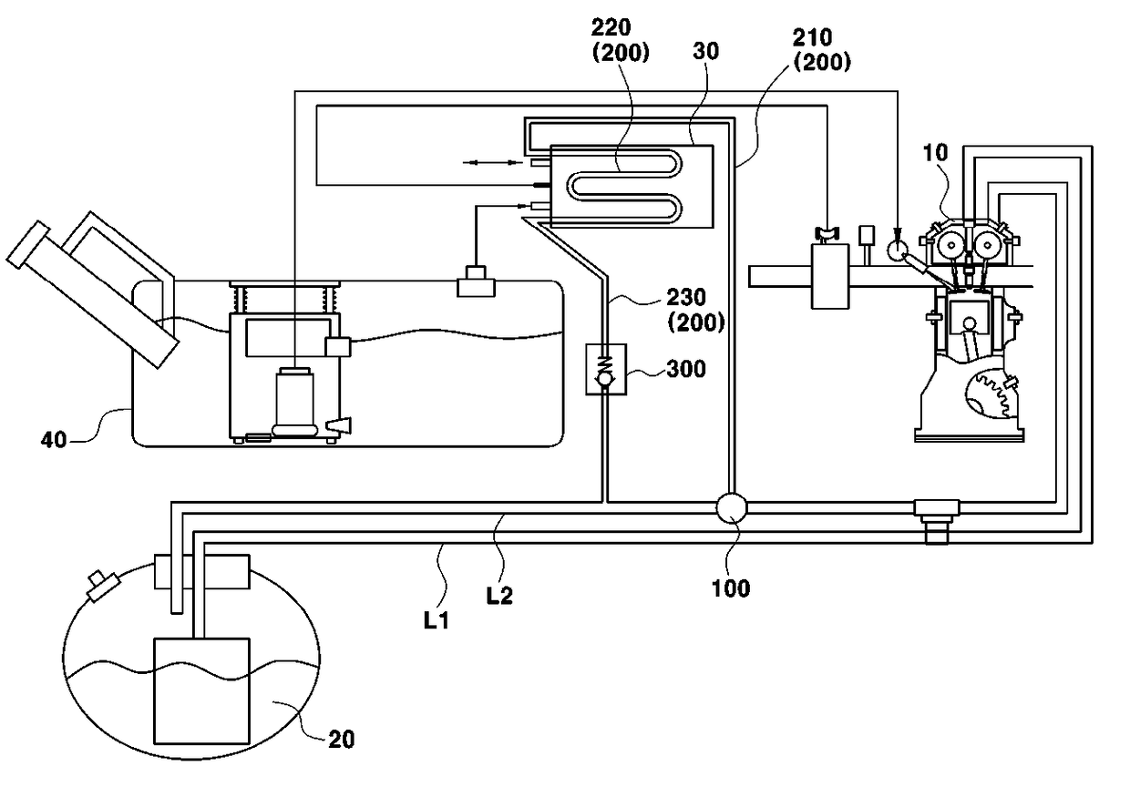
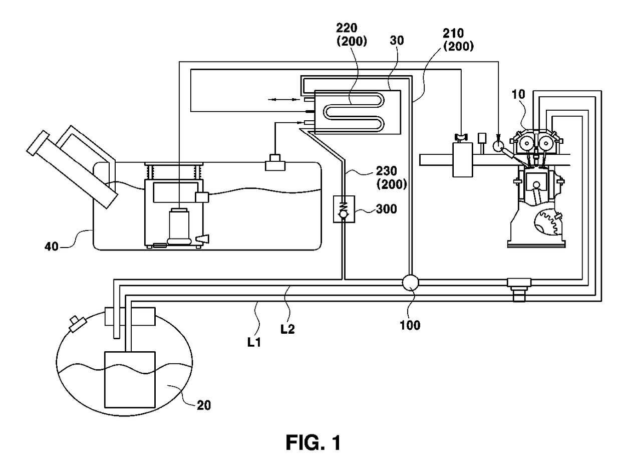
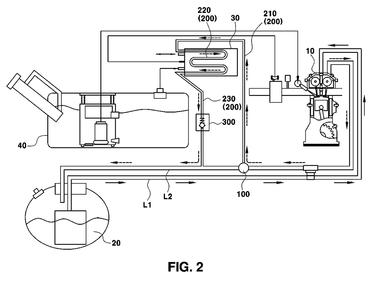
Fuel system for bi-fuel vehicle and method of filling bi-fuel vehicle with LPG fuel using the same

a fuel system and vehicle technology, applied in the direction of machines/engines, electric control, combustion air/fuel air treatment, etc., to achieve the effect of reducing the temperature of lpg fuel

Active Publication Date: 2017-04-20
HYUNDAI MOTOR CO LTD
View PDF6 Cites 0 Cited by
  • Summary
  • Abstract
  • Description
  • Claims
  • Application Information

AI Technical Summary

Benefits of technology

The present invention provides a fuel system for a bi-fuel vehicle and a method for filling it with liquefied petroleum gas (LPG) fuel. The system includes a valve that controls the pressure in the LPG tank, allowing the LPG fuel to pass through a canister and have a heat exchange, which decreases the temperature of the fuel. This decreased temperature makes it easier to fill the vehicle with LPG fuel, regardless of external temperatures. The invention also improves detachment efficiency in the canister by reusing lost thermal energy from the LPG fuel.

Problems solved by technology

Recently, vehicles that use electricity or hydrogen as a power source have been produced, but these vehicles have not yet been widely used, and gasoline, gas or the like is typically used as fuel of the vehicle.
However, in the case of the bi-fuel vehicle, at the time of charging a vehicle with liquefied petroleum gas (LPG) fuel in summer, a temperature in an LPG tank in the vehicle is increased because of an outside temperature in summer, and pressure in the LPG tank is increased accordingly, and as a result, the pressure in the LPG tank becomes higher than a charging pressure of an LPG fuel station, which may result in a problem of filling the vehicle with LPG.

Method used


Image

  • Fuel system for bi-fuel vehicle and method of filling bi-fuel vehicle with LPG fuel using the same
  • Fuel system for bi-fuel vehicle and method of filling bi-fuel vehicle with LPG fuel using the same
  • Fuel system for bi-fuel vehicle and method of filling bi-fuel vehicle with LPG fuel using the same

Examples


Embodiment Construction

[0037]It is understood that the term “vehicle” or “vehicular” or other similar term as used herein is inclusive of motor vehicles in general such as passenger automobiles including sports utility vehicles (SUV), buses, trucks, various commercial vehicles, watercraft including a variety of boats and ships, aircraft, and the like, and includes hybrid vehicles, electric vehicles, plug-in hybrid electric vehicles, hydrogen-powered vehicles and other alternative fuel vehicles (e.g. fuels derived from resources other than petroleum). As referred to herein, a hybrid vehicle is a vehicle that has two or more sources of power, for example both gasoline-powered and electric-powered vehicles.

[0038]The terminology used herein is for the purpose of describing particular embodiments only and is not intended to be limiting of the invention. As used herein, the singular forms “a,”“an” and “the” are intended to include the plural forms as well, unless the context clearly indicates otherwise. It will...


PUM


Abstract

A fuel system for a bi-fuel vehicle, which is provided with an engine and an LPG tank connected to each other through a fuel supply line and a fuel return line through which liquefied petroleum gas (LPG) fuel passes, includes: a 3-way valve which is installed in the fuel return line, and selectively opened and closed to move returning LPG fuel to a canister connected with a fuel tank; and a return tube, which branches off from the fuel return line, installed so that the returning LPG fuel passes through the canister in accordance with an operation of the 3-way valve, allowing the LPG fuel of which the temperature is decreased by heat exchange while the LPG fuel passes through the canister to move to the fuel return line.

Description

CROSS-REFERENCE TO RELATED APPLICATION[0001]This application claims under 35 U.S.C. §119(a) the benefit of Korean Patent Application No. 10-2015-0145756 filed on Oct. 20, 2015, the entire contents of which are incorporated herein by reference.BACKGROUND[0002](a) Technical Field[0003]The present disclosure relates to a fuel system for a bi-fuel vehicle and a method of charging a bi-fuel vehicle with liquefied petroleum gas (LPG) fuel using the same, more particularly, to a fuel system that decreases pressure in an LPG tank for a bi-fuel vehicle.[0004](b) Description of the Related Art[0005]In general, an engine for a vehicle combusts fuel to reciprocally move pistons in order to obtain power required to drive the vehicle, and the reciprocating motion of the pistons is converted into rotational motion, thereby driving the vehicle.[0006]As described above, the combustion of fuel is an essential element for driving the vehicle.[0007]Recently, vehicles that use electricity or hydrogen as...

Claims


Application Information

Patent Timeline
IPC IPC(8): F02M21/02F02D41/00F02M25/08F02M33/08F02D19/02
CPCF02M21/0212F02M21/0236F02M21/0224F02D41/0042F02D19/027F02M25/0854F02M25/089F02M33/08F02D19/022F02M21/0218F02M31/20F02M31/205F02D41/0025F02D41/0027F02M25/08F02M2025/0881Y02T10/30
Inventor KIM, CHANG HANKIM, JONG KIPARK, JAE HWALEE, JAE MIN
Owner HYUNDAI MOTOR CO LTD
Learn More