
Magnetic resonance imaging with RF noise detection coils

Active Publication Date: 2017-04-20
KONINKLJIJKE PHILIPS NV
View PDF4 Cites 38 Cited by
  • Summary
  • Abstract
  • Description
  • Claims
  • Application Information

AI Technical Summary

Benefits of technology

The patent describes a method for removing noise from magnetic resonance images by detecting and correcting the RF noise events using a noise calibration. The noise calibration is frequency, phase, and amplitude dependent, which allows for a more accurate and efficient removal of noise from the imaging data. The method can be implemented using machine-executable instructions and can improve the quality of the resulting magnetic resonance image.

Problems solved by technology

However, spurious RF noise during the MRI scan can interfere with the measurement of the RF signals emitted by the nuclear spins.
A disadvantage to using the such an RF cage is that it uses large amounts of metal such as copper and is expensive to build.

Method used


Image

  • Magnetic resonance imaging with RF noise detection coils
  • Magnetic resonance imaging with RF noise detection coils
  • Magnetic resonance imaging with RF noise detection coils

Examples


Embodiment Construction

[0067]Like numbered elements in these figures are either equivalent elements or perform the same function. Elements which have been discussed previously will not necessarily be discussed in later figures if the function is equivalent.

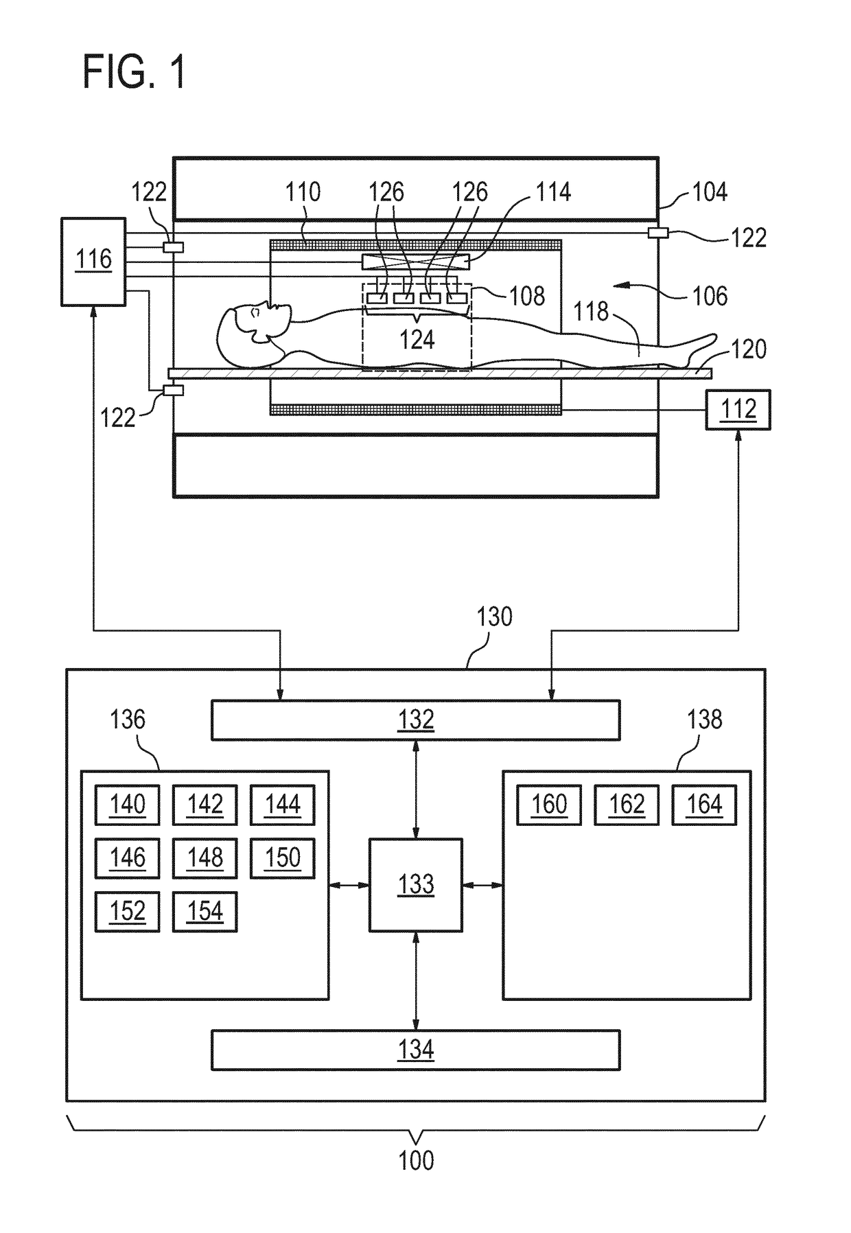
[0068]FIG. 1 shows an example of a magnetic resonance imaging system 100. The magnetic resonance imaging system 100 comprises a magnet 104. The magnet 104 is a superconducting cylindrical type magnet 104 with a bore 106 through it. The use of different types of magnets is also possible for instance it is also possible to use both a split cylindrical magnet and a so called open magnet. A split cylindrical magnet is similar to a standard cylindrical magnet, except that the cryostat has been split into two sections to allow access to the iso-plane of the magnet, such magnets may for instance be used in conjunction with charged particle beam therapy. An open magnet has two magnet sections, one above the other with a space in-between that is large enough to ...


PUM


Abstract

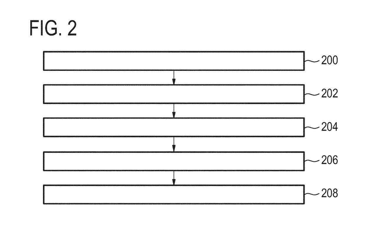
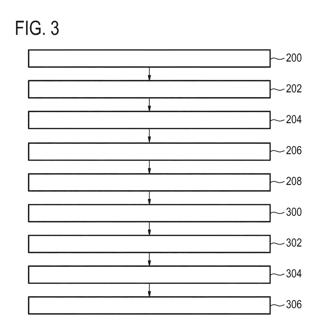
The invention provides for a magnetic resonance imaging system (100) for acquiring magnetic resonance data (142,144) from an imaging zone (108). Execution of the instructions causes a processor (133) controlling the MRI system to: acquire (200) imaging magnetic resonance data (142) with radio frequency excitation of the radio frequency system enabled; acquire (202) noise radio frequency data (148) using at least one RF noise detection coil, wherein the noise radio frequency data is acquired simultaneously with the imaging magnetic resonance data; acquire (204) calibration magnetic resonance data (144) with radio frequency excitation of the radio frequency system disabled; acquire (206) reference radio frequency data (146) using the at least one RF noise detection coil, wherein the reference radio frequency data is acquired simultaneously with the calibration magnetic resonance data; and calculate (208) a noise calibration (150) using the reference radio frequency data and the calibration magnetic resonance data.

Description

TECHNICAL FIELD OF THE INVENTION[0001]The invention relates to magnetic resonance imaging, in particular to magnetic resonance imaging in the presence of spurious RF signals.BACKGROUND OF THE INVENTION[0002]A large static magnetic field is used by Magnetic Resonance Imaging (MRI) scanners to align the nuclear spins of atoms as part of the procedure for producing images within the body of a patient. This large static magnetic field is referred to as the BO field or the main magnetic field.[0003]During an MRI scan, Radio Frequency (RF) pulses generated by a transmitter coil cause perturbations to the local magnetic field, and RF signals emitted by the nuclear spins are detected by a receiver coil. These RF signals are used to construct the MRI images. These coils can also be referred to as antennas. Further, the transmitter and receiver coils can also be integrated into a single transceiver coil that performs both functions. It is understood that the use of the term transceiver coil a...

Claims


Application Information

Patent Timeline
IPC IPC(8): G01R33/565G01R33/36G01R33/58G01R33/422
CPCG01R33/5659G01R33/583G01R33/3607G01R33/422G01R33/36
Inventor HARVEY, PAUL ROYSTONDUIJVESTIJN, MICHAEL JOZEFLORENC, STEVE
Owner KONINKLJIJKE PHILIPS NV
Learn More