
Resonant high current density transformer

a high current density, transformer technology, applied in the direction of basic electric elements, electrical equipment, inductance, etc., can solve the problems of laborious interspersed insulation sleeves and twisting wires, the transformer cannot be reduced, and the output wiring or wire twisting is difficult. achieve the effect of increasing the effective conductive cross-sectional area, high current density, and effectively reducing the size of the transformer

Active Publication Date: 2017-04-20
YUJING TECH CO LTD
View PDF2 Cites 2 Cited by
  • Summary
  • Abstract
  • Description
  • Claims
  • Application Information

AI Technical Summary

Benefits of technology

The present invention provides a resonant high current density transformer that uses metal plates instead of traditional wires, which increases the effective conductive cross-sectional area in a unit area and reduces the size of the transformer. The primary and secondary windings can be placed on separate bobbins, which makes assembly easier and increases processing efficiency. The two bobbins are fastened to each other by mechanical structures, which regulates the distance between them and controls the characteristics of the transformer such as leakage inductance.

Problems solved by technology

However, with these winding structures with multi-strand wires (enameled wires), it can be difficult to strip off the insulation layers, there might also be difficulties in output wiring or wire twisting due to the large number of strands.
Furthermore, gaps are created between wires (enameled wires), so the size of the transformer cannot be reduced.
2. In conventional LLC transformer structures, the primary and secondary windings are wound on different locations of a single bobbin (winding base), in addition to winding, interspersing insulation sleeves and twisting wires are labor intensive.
However, if the primary and secondary windings are provided on the same bobbin, distances associated with safety regulations may not be long enough, and leakage inductance cannot be easily modified, so an additional inductor is needed as a resonant inductor.
On the other hand, if the primary and secondary windings are provided on the two bobbins, a constant distance between the two bobbins is difficult to maintain, which results in drifts in characteristics such as the leakage inductance.

Method used


Image

  • Resonant high current density transformer
  • Resonant high current density transformer
  • Resonant high current density transformer

Examples


Embodiment Construction

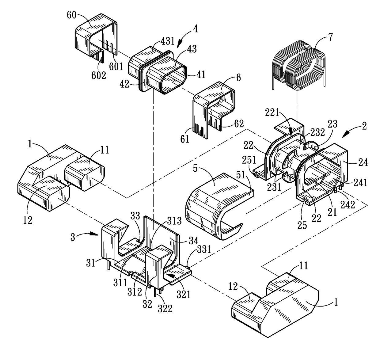
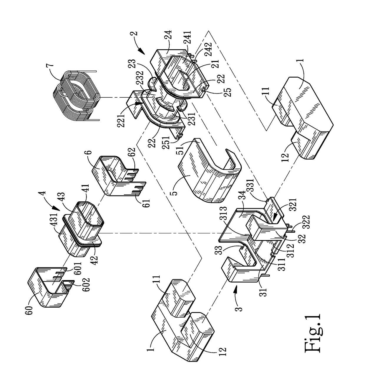
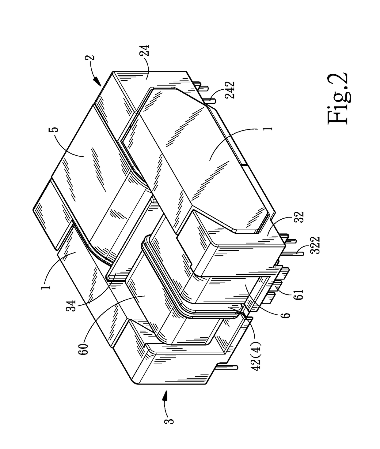
[0028]Referring to FIGS. 1 to 3, it can be understood that the structure of the present invention mainly includes: two cores 1, a first bobbin 2, a bobbin mount 3, a second bobbin 4, a separating cover 5, a metal plate 6 and a primary winding 7; wherein first and second side posts 11 and 12 extending in the same direction from the two sides of each of the cores 1. When the two cores 2 abut against each other with the two first side posts 11 facing each other and the two second side posts 12 facing each other, a magnetic loop is formed.

[0029]The first bobbin 2 is provided with a penetrating first through-hole 21, which envelops the first side posts 11 on the same side of the two cores 1 at their outer peripheries. A side plate 22 is provided on the outer periphery of either end of the first through-hole 21. A spacer 23 is provided between the two side plates 22. Two coil slots 231 are formed on the two sides of the spacer 23, respectively. A plurality of gaps 232 are provided on the ...


PUM


Abstract

A resonant high current density transformer including two cores that are abut against each other with their first and second side posts on two sides thereof. A first bobbin envelops the first side posts on the same side of the two cores. A side plate is provided on either end of the first bobbin. The space between the two side plates is divided into two coil slots with a spacer, and at least a wire is wound in each coil slot to form a primary winding. A further second bobbin envelops the second side posts on the same side of the two cores. The outer periphery of the second bobbin is divided into two winding regions by another spacer, and a metal plate envelops each of the winding regions to form a secondary winding. A bobbin mount is disposed at the external flank of the second bobbin with a barrier plate at a side thereof for separating the first and the second bobbins. An insulating separating cover is provided on a side of the first bobbin closer to the bobbin mount, and the two ends of the separating cover cover the top and bottom sides of the first bobbin, respectively.

Description

CROSS REFERENCE TO RELATED APPLICATIONS[0001]This non-provisional application claims priority under 35 U.S.C. §119(a) on Patent Application No. 104133675, filed in Taiwan, Republic of China on Oct. 14, 2015, the entire contents of which are hereby incorporated by reference.BACKGROUND OF THE INVENTION[0002]Field of the Invention[0003]The invention relates to a resonant high current density transformer, and more particularly, to a reduced-sized resonant transformer capable of increasing power density and easy of automated processing.[0004]Description of the Related Art[0005]In power supply system for electronic products such as LCD TVs, a main type of transformers used is transformers with leakage inductance property (such as LLC transformer) that reduces switching loss and noise.[0006]In TW Utility Patent Publication No. M333646 titled “Improvement of Leakage-Inductance-type Resonant Transformer”, the transformer mainly includes: an outer bobbin provided with a first through-hole and...

Claims


Application Information

Patent Timeline
IPC IPC(8): H01F27/34H01F27/32H01F27/24H01F27/28
CPCH01F27/346H01F27/24H01F27/325H01F27/28H01F27/2866H01F27/306H01F27/326H01F38/10
Inventor YANG, SEN-TAI
Owner YUJING TECH CO LTD
Learn More