Cambelt, in particular a cambelt suitable for agricultural machinery

a cambelt and agricultural machinery technology, applied in the field of cambelts, can solve the problems of reducing the reference diameter, adversely affecting the intermeshing of the system, and high wear on the surface of the carrier means and the rivet plate which comes into contact, and achieves the effects of low noise, low wear, and simple installation of the fastening means

Inactive Publication Date: 2017-04-27
ARNOLD JAGER HLDG GMBH
View PDF9 Cites 11 Cited by
  • Summary
  • Abstract
  • Description
  • Claims
  • Application Information

AI Technical Summary

Benefits of technology

[0010]An object of the present invention, therefore, is to provide a cam belt of this type having low wear and low noise, with simple installation of the fastening means.

Problems solved by technology

The generally large radial forces on the deflection points and the customary conveying speeds of 0.5 to 8 m / s, as well as the mechanical contact in conjunction with abrasive materials such as soil, dirt, and harvested crop, over the long-term result in a high level of wear on surfaces of the carrier means and of rivet plates which come into contact.
This causes a reduction in the reference diameters over time, resulting in increasingly larger differences with respect to the cam division of the cam belt, which adversely affects the intermeshing of the system.
In addition, this results in considerable running noise due to the contact between the carrier means of the cam wheels and the rivet plates.
If the wear continues until the rivet head is worn down, the functional element detaches from the cam belt, which may result in failure of the entire system.
One disadvantage is that vulcanization of the fastening means is relatively complicated.
Here as well, however, metal-to-metal contact between the drive means and the fastening means is not avoided.

Method used


Image

  • Cambelt, in particular a cambelt suitable for agricultural machinery
  • Cambelt, in particular a cambelt suitable for agricultural machinery
  • Cambelt, in particular a cambelt suitable for agricultural machinery

Examples


Embodiment Construction

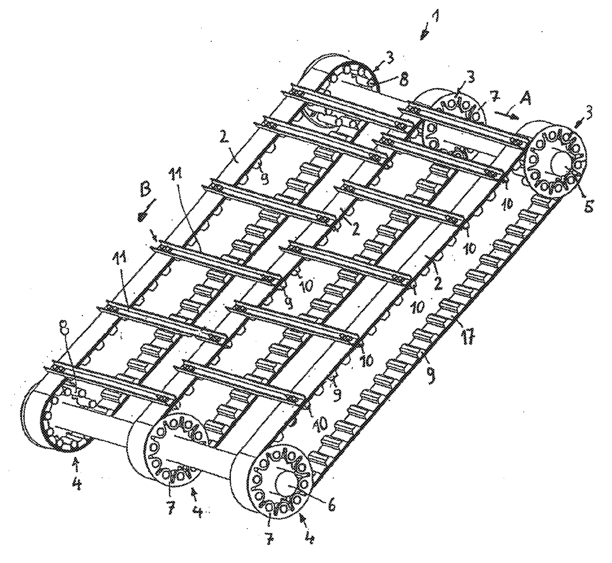
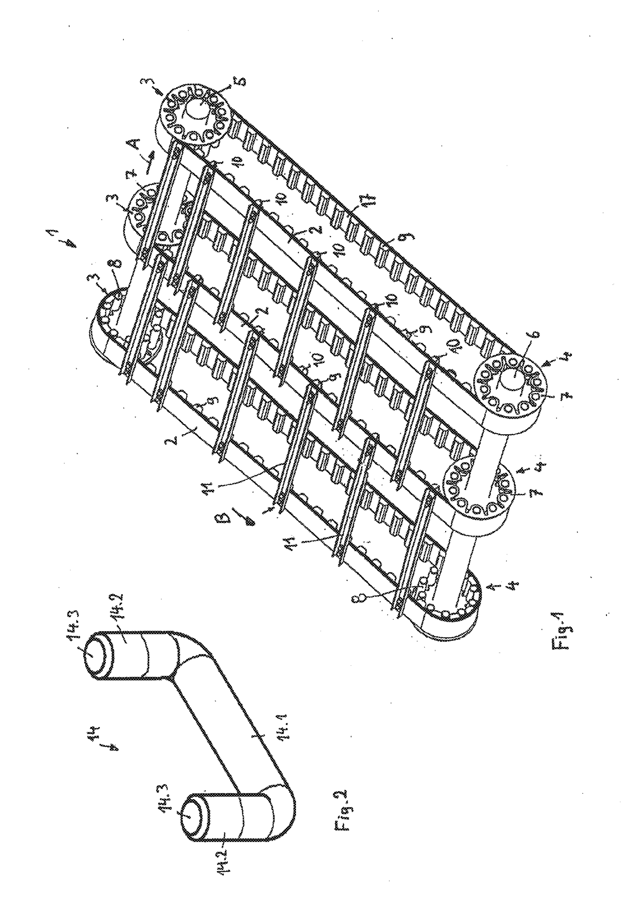
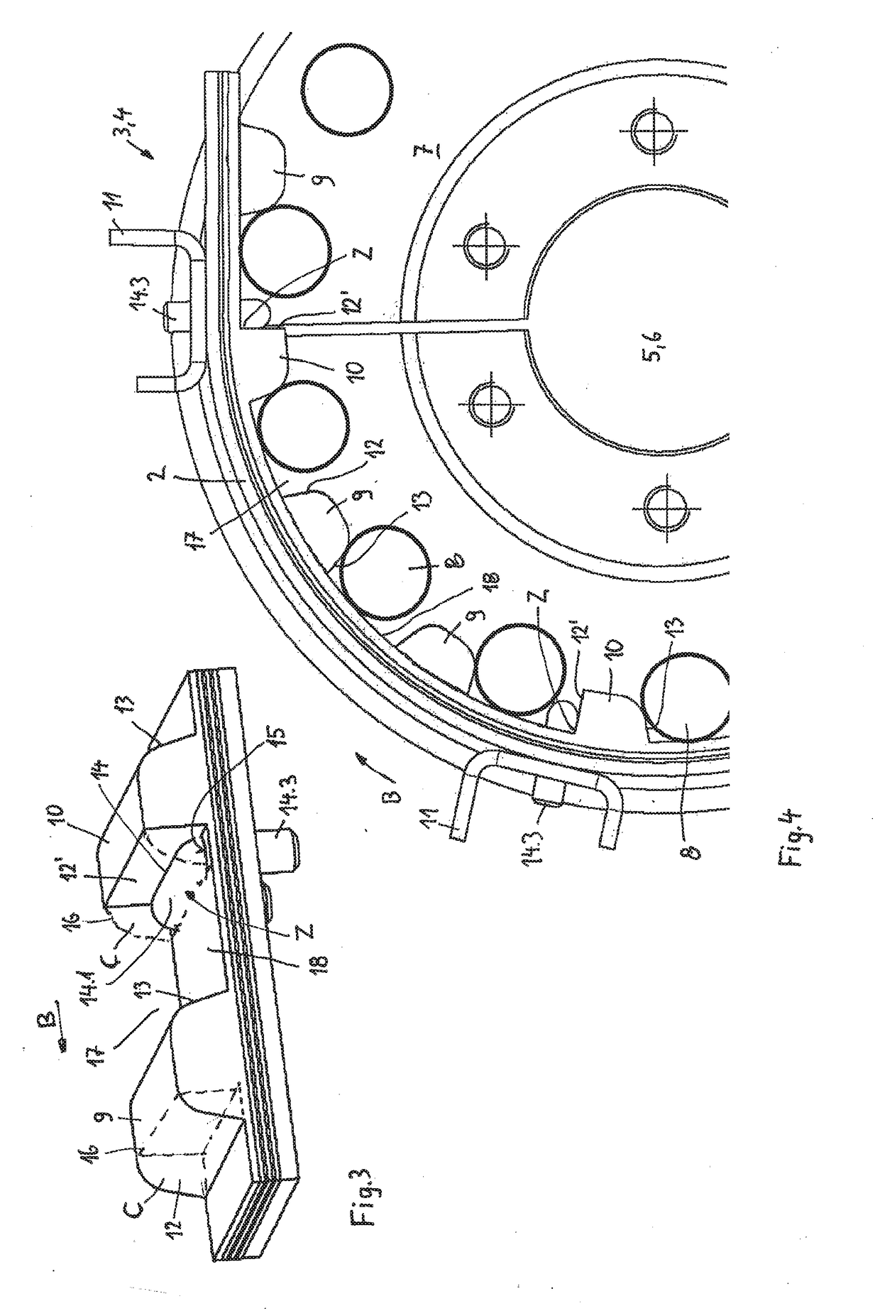
[0028]FIG. 1 shows an inclined conveyor 1 for a combine harvester, having three cam belts 2 extending in parallel. The inclined conveyor conveys harvested crop in an undershot manner to a threshing unit of the combine harvester, not illustrated. The cam belts 2 are deflected via upper cam wheels 3 and lower cam wheels 4, which in this exemplary embodiment are designed as welded structures. A cast structure instead of a welded structure is also possible. The upper cam wheels 3 rest on a driven shaft 5, while the lower cam wheels 4, which rest on a shaft 6, are carried by the driven cam belts 2. The cam wheels 3 and 4 have a hub plate 7 that is connected in a rotatably fixed manner to the shafts 5, and carrier means in the form of perpendicularly protruding cylindrical bolts 8 are welded at the circumference of the cam wheels.

[0029]In a first embodiment of the invention, the cam belts 2 have two types of cams: cams 9 that are used solely for driving the cam belts 2 and cams 10 that ar...


PUM


Abstract

Cam belt, particularly for agricultural machinery, produced from a polymer provided with reinforcement inserts, has cams on the inner side of the cam belt that are used to drive cam belt. A first flank faces in the running direction of cam belt and a second flank faces in opposite direction. Cams are spaced apart from one another by gaps in a predefined division, and gaps are delimited by first flank and second flank of two adjoining cams and a base which connects two flanks. During operation of cam belt carrier of a cam wheel resting against second flank of one of adjoining cams and against the base of a gap engage with the gaps. On outer side of belt, functional elements are fixed by a fastener which from inner side of the belt passes through the cam belt and the functional elements via at least one through hole.

Description

CROSS-REFERENCE TO RELATED APPLICATIONS[0001]This application claims the priority of German Application No. 10 2015 118 143.6, filed Oct. 23, 2015, which is incorporated herein by reference.FIELD OF THE INVENTION[0002]The present invention relates to a cam belt. In particular, this invention relates to a cam belt suitable for agricultural machinery.BACKGROUND OF THE INVENTION[0003]The present invention relates to a cam belt, in particular for agricultural machinery.[0004]Conveyor belts which have cam belts as traction means are frequently used, in particular in the field of agriculture. These types of conveyor belts usually have two or more cam belts which run in parallel to one another and are connected to one another by functional elements, for example carriers. On their inner side, the cams belts have evenly interspaced cams which are separated by gaps and which in each case circulate around a driven cam wheel and a carried cam wheel. On their periphery the cam wheels have carrie...

Claims


Application Information

Patent Timeline
Patent Type & Authority Applications(United States)
IPC IPC(8): B65G17/42A01D61/02B65G15/52
CPCB65G17/42A01D61/02B65G15/52A01D61/008A01D2017/103B65G15/42B65G15/44B65G19/10B65G15/12B65G19/24
Inventor JAGER, SEBASTIANSCHMIDT, NICK
Owner ARNOLD JAGER HLDG GMBH
Why Eureka
Try Eureka