Arc resistant power terminal

a power terminal and arc resistance technology, applied in the direction of connection insulation, coupling device details, coupling device connection, etc., can solve the problems of affecting the likelihood of accidental shorting, arc tracking at the terminal connection point, and shutting down the power supply system, so as to improve the overall electrical properties of the connection, improve the grip function, and improve the effect of electrical and mechanical features

Active Publication Date: 2017-04-27
CARLISLE INTERCONNECT TECH
View PDF5 Cites 7 Cited by
  • Summary
  • Abstract
  • Description
  • Claims
  • Application Information

AI Technical Summary

Benefits of technology

[0070]The structure of the oxide breaker element provides not only the ability to break through the oxide layer on the conductor strand, but also improves the electrical and mechanical features of the invention. For example, electrically, the construction of the oxide breaker element increases the surface area of the crimp, and the contact with the conductor, to improve the overall electrical properties of the connection in the transition from the wire to the terminal. Furthermore, the oxide breaker element 158 increases the grip function at the contact portion 138, and increases the pull force necessary to remove the wire 20 from terminal 100.

Problems solved by technology

The problem with shorting or arcing has become a particular problem within the aerospace industry.
Greater us of electrical systems and the respective higher voltages and frequencies directly impact the likelihood of accidental shorting and arc tracking at the terminal connection points.
Accidental shorting or arcing between the different voltage phases that are used in such systems can cause damage, and may potentially shut the power down for a system.
Furthermore, space constraints exacerbate the issue as the terminals are often positioned close to one another at a terminal block or at equipment connection points.
Contaminants between the terminals may also cause arcing issues.
If the various contaminants can create a low enough current resistance paths between the terminals, then arc tracking may start and progress to the point of significant damage.
However, such methods often involve mechanical dividers or require increasing separation distances, which may not always be feasible.
The various physical dividers are not sufficient to prevent the arc tracking.

Method used


Image

  • Arc resistant power terminal
  • Arc resistant power terminal
  • Arc resistant power terminal

Examples


Embodiment Construction

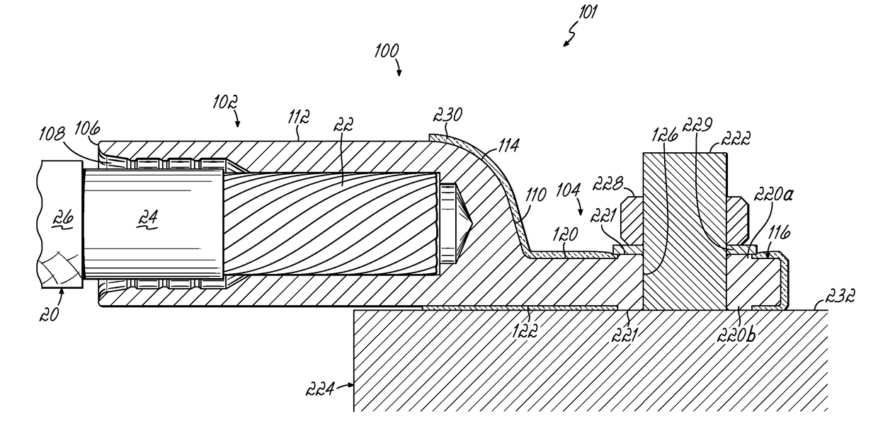
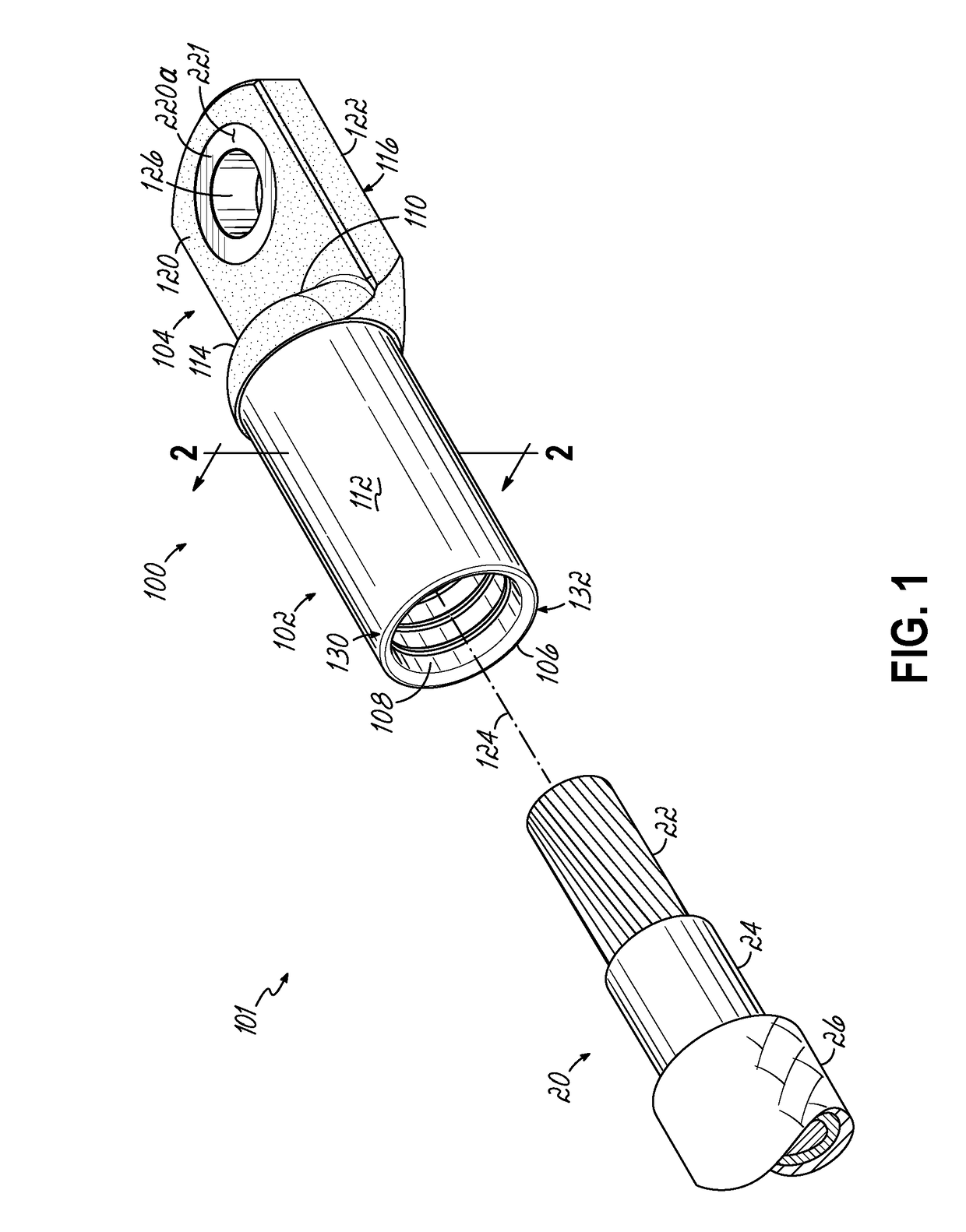
[0034]With reference to FIG. 1, in one embodiment of the invention, an arc resistant electrical terminal 100 in accordance with features of the invention is incorporated into a cable or wire assembly 101. The arc resistant terminal 100 includes a body made from a suitable electrically conductive material, such as a metal such as copper or aluminum. In one embodiment, terminal 100 is a solid piece of 1100 Aluminum per ASTM B221. The terminal has a body with a solid or integral construction and includes a wire receiving portion 102 and an integral mount portion 104. The terminal 100 is incorporated into the cable assembly 101 with a suitable wire or conductor 20, as shown in FIG. 1. Conductor 20, for example, might be a solid or stranded copper or aluminum wire having a center conductor 22 and an insulating sheath 24. In one embodiment, the conductor 20 connected with the terminal may also include an abrasion sheath 26.

[0035]Referring to FIGS. 1 and 3, embodiments of an arc-resistant ...


PUM


Abstract

An arc-resistant electrical terminal includes a mount portion and a wire receiving portion formed of an electrically conductive material. The wire receiving portion is configured to be crimped onto a wire. The mount portion includes a solid tongue having opposing face surfaces. An aperture is formed between the opposing face surfaces for connecting the terminal to a connection point. A layer of insulation material is formed on at least a portion of the tongue for preventing arcing at a connection point. A raised boss is formed to surround the aperture on at least one of the opposing face surfaces of the tongue, the raised boss providing an electrically conductive surface of the terminal free from the layer of insulation material for connection to a connection point.

Description

FIELD OF THE INVENTION[0001]This present invention relates generally to electrical connectors or terminals, and particularly to improving the performance of such terminals.BACKGROUND OF THE INVENTION[0002]Electrical connectors, or terminals for terminating a power cable connection, are often connected side-by-side to grounding studs, to power strips or on top of each other, such as on a terminal block or on a power strip. They provide power to circuitry and electronics of a system, vehicle, or device, and thus, are often coupled in a tight configuration to address space constraints, such as in an aircraft. The phrases lug, terminal lug, and terminal will be used interchangeably in this application to refer to such terminal connectors.[0003]While wire and cables that are terminated with such terminal are insulated along their length, the terminals themselves are exposed for making electrical contact with other terminals, terminal blocks, or equipment connection points. As a result, a...

Claims


Application Information

Patent Timeline
Patent Type & Authority Applications(United States)
IPC IPC(8): H01R4/70H01R4/34
CPCH01R4/34H01R4/70H01R4/206H01R4/30H01R9/24H01R11/09H01R11/12H01R43/24H01R13/6485H01R43/048
Inventor ARENBURG, WILLIAM L.SUTHERLAND, JACK EDGER
Owner CARLISLE INTERCONNECT TECH
Why Eureka
Try Eureka