Moving-magnet type linear motor controlling system and manufacturing method of parts

a linear motor and control system technology, applied in the direction of multi-motor speed/torque control, dynamo-electric components, dynamo-electric machines, etc., can solve the problems of difficult to highly accurately control the mover, the plurality of movers cannot be highly accurately controlled, and the casing deformation, etc., to achieve accurate calculation and high accuracy control

Active Publication Date: 2017-04-27
CANON KK
View PDF9 Cites 15 Cited by
  • Summary
  • Abstract
  • Description
  • Claims
  • Application Information

AI Technical Summary

Benefits of technology

[0011]According to an embodiment of the invention, a ratio of the currents which are supplied to the coil units is determined on the basis of the positions of the plurality of carts and an impedance and thrust characteristics of each of the plurality of coil units. Thus, even when the cart is contr...

Problems solved by technology

If such a heat generation is propagated to a casing or the like, a deformation of the casing or the like increases and it is difficult to highly accurately control the mover.
According to the technique disclosed in Japanese Patent Application Laid-Open No. 2011-50220, since it relates to the system in which only one mover is controlled per stator, control is made in such a manner t...

Method used


Image

  • Moving-magnet type linear motor controlling system and manufacturing method of parts
  • Moving-magnet type linear motor controlling system and manufacturing method of parts
  • Moving-magnet type linear motor controlling system and manufacturing method of parts

Examples


first embodiment

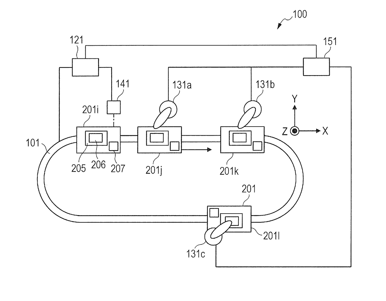
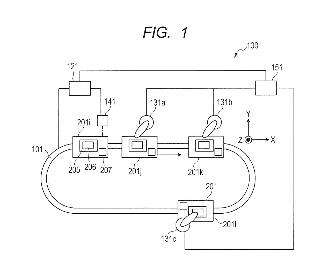
[0027]A work machining system 100 as a moving-magnet type linear motor controlling system according to the first embodiment of the invention will be described hereinbelow with reference to the drawings. FIG. 1 is a schematic diagram illustrating a whole construction of the work machining system 100. The work machining system 100 has a conveying path 101, a conveying system controller 121, processing apparatuses 131a to 131c, an RFID reader 141, a processing controller 151, and carts 201i to 201l and is disposed on a horizontal mount (not shown).

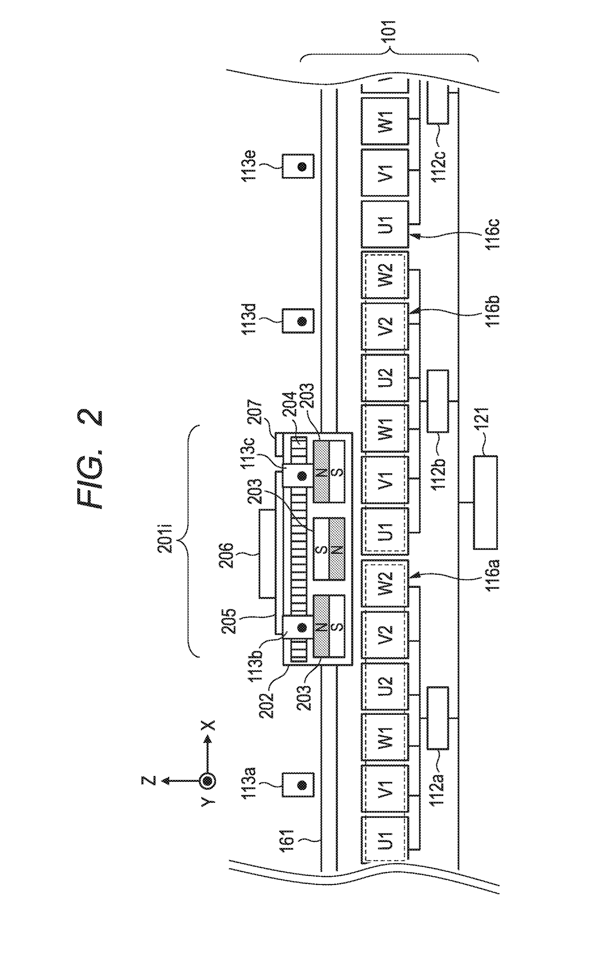
[0028]The carts 201i to 201l are disposed on the conveying path 101 so as to be movable along a guide rail 161, which will be described hereinlater. The conveying system controller 121 has a CPU (Central Processing Unit) and a memory (not shown) such as RAM, ROM, or the like and controls the running operations of all of the carts 201i to 201l on the conveying path 101. Information such as thrust constant profile, impedance of a coil unit 116,...

second embodiment

[0056]A moving-magnet type linear motor controlling system according to the second embodiment of the invention will be described hereinbelow. The second embodiment differs from the first embodiment with respect to a point that a plurality of carts are controlled, and other constructions are common. Therefore, a description of the common portions is omitted.

[0057]FIG. 8 is a layout diagram of carts in the work machining system 100 according to the embodiment. As illustrated in FIG. 8, the carts 201i and 201j exist in an interval between the coil units 116a to 116c. The cart 201i (first cart) exists at a position where it can receive the thrusts from the coil unit 116a (second coil unit) and the coil unit 116b (first coil unit). The cart 201j (second cart) exists at a position where it can receive the thrusts from the coil unit 116b (first coil unit) and the coil unit 116c (third coil unit).

[0058]In the case where a processing apparatus 131 respectively executes a predetermined proces...

third embodiment

[0063]A moving-magnet type linear motor controlling system according to the third embodiment of the invention will be described hereinbelow. The third embodiment differs from the first embodiment with respect to a point that a plurality of carts are controlled, and other constructions are common. Therefore, a description of the common portions is omitted.

[0064]FIG. 10 is a layout diagram of carts in the work machining system 100 according to the embodiment. As illustrated in FIG. 10, the cart 201i (first cart) exists at a position where it can receive the thrusts from the coil unit 116a (second coil unit) and the coil unit 116b (first coil unit). The cart 201j (second cart) exists at a position where it can receive the thrust from only the coil unit 116b (first coil unit). An interval between the carts 201i and 201j illustrated in FIG. 10 is narrower than the interval between the carts 201i and 201j in FIG. 8 described in the second embodiment. A description will be made in detail w...


PUM


Abstract

A moving-magnet type linear motor controlling system which can highly accurately control carts even when a plurality of coil units apply forces to the carts is provided. The moving-magnet type linear motor controlling system has: a plurality of coil units having a plurality of coils; a position detecting unit for detecting the positions of the plural carts which are moved along the plurality of coil units; and a controlling unit for determining a ratio of currents which are supplied to the plural coil units on the basis of the positions of the plural carts and an impedance and thrust characteristics of each of the plural coil units.

Description

BACKGROUND OF THE INVENTION[0001]Field of the Invention[0002]The present invention relates to a linear motor controlling system which is used for a driving or the like of carts of a conveying apparatus for factory automation (FA) and, more particularly, to a controlling system of a moving-magnet type linear motor.[0003]Description of the Related Art[0004]Generally, in a factory-automated production line for assembling industrial products, a conveying system for conveying parts or the like is used. As such a conveying system, a moving-magnet type linear motor system having a mover provided with a plurality of permanent magnets, coils arranged along a moving path of the mover, and current controllers for supplying currents to the coils has been proposed.[0005]Japanese Patent Application Laid-Open No. H05-30784 proposes a driver controlling apparatus of a vertical type linear motor. According to such a driver controlling apparatus, it has a plurality of armature coils, an exciting curr...

Claims


Application Information

Patent Timeline
IPC IPC(8): H02P6/04H02P6/00H02P25/06
CPCH02P6/04H02P2006/045H02P6/006H02P25/06H02K41/031
Inventor YAMAMOTO, TAKESHI
Owner CANON KK
Why Eureka
Try Eureka