Eureka AIR delivers breakthrough ideas for toughest innovation challenges, trusted by R&D personnel around the world.

Bathwater circulating system and method of operating same

Inactive Publication Date: 2017-05-04
FRANZ KALDEWEI
View PDF0 Cites 4 Cited by
  • Summary
  • Abstract
  • Description
  • Claims
  • Application Information

AI Technical Summary

Benefits of technology

The invention is related to a bathwater circulating system that reduces noise and impairment to the user's well-being. The system eliminates a fluid-settling chamber typically used in known designs, which can amplify noise. Additionally, the system allows for better mixing of ambient air and bathwater through a long output conduit, reducing the amount of bubbling and flow noises. The invention also suggests using normal bath additives such as bath oil, salt, alcohol, soap, or the like to prevent coalescence of microbubbles and form smaller, more pleasant bubbles. Furthermore, the invention recommends using a centrifugal pump that provides good mixing of bathwater and ambient air at a low cost and low noise level.

Problems solved by technology

Furthermore, eliminating larger bubbles in a fluid-settling chamber by bursting individual bubbles, according to the state of the art, leads to higher operating noise which, depending on the design, can also be perceived as a sort of bubbling.
Also, changes in cross-section occur at the transitions in the fluid-settling chamber, which can also lead to flow noises.

Method used


Image

  • Bathwater circulating system and method of operating same
  • Bathwater circulating system and method of operating same
  • Bathwater circulating system and method of operating same

Examples


Embodiment Construction

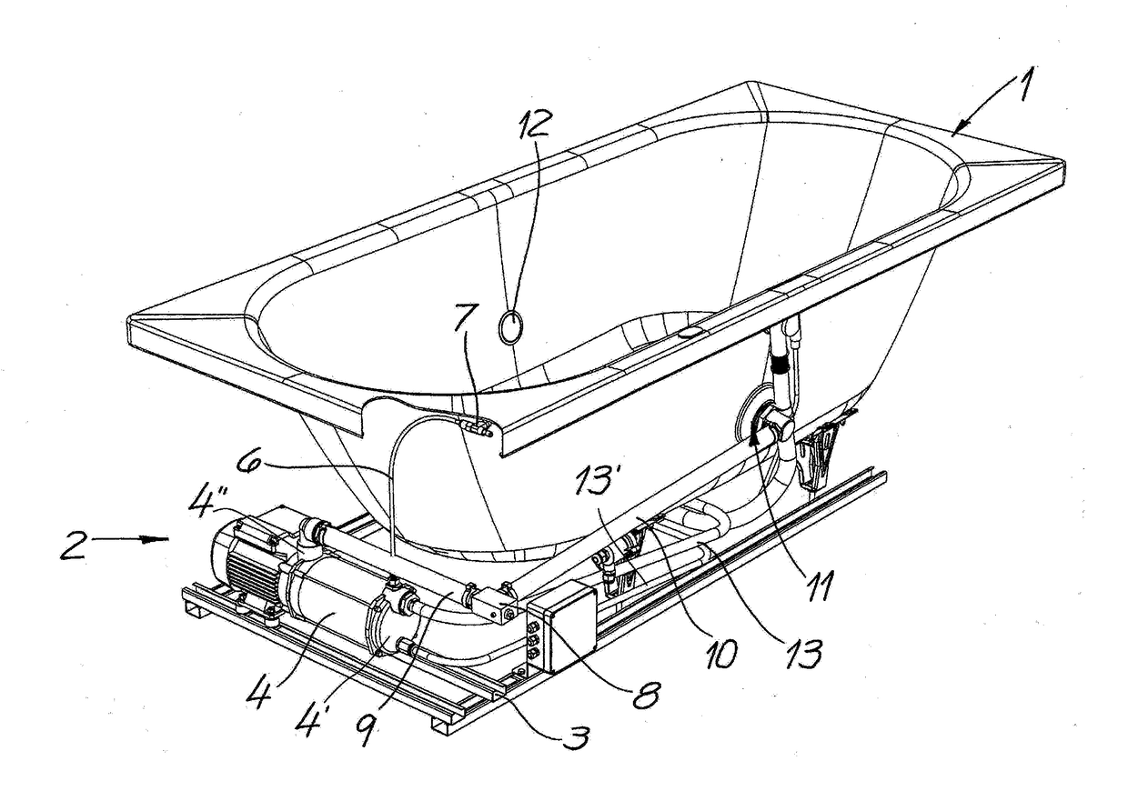
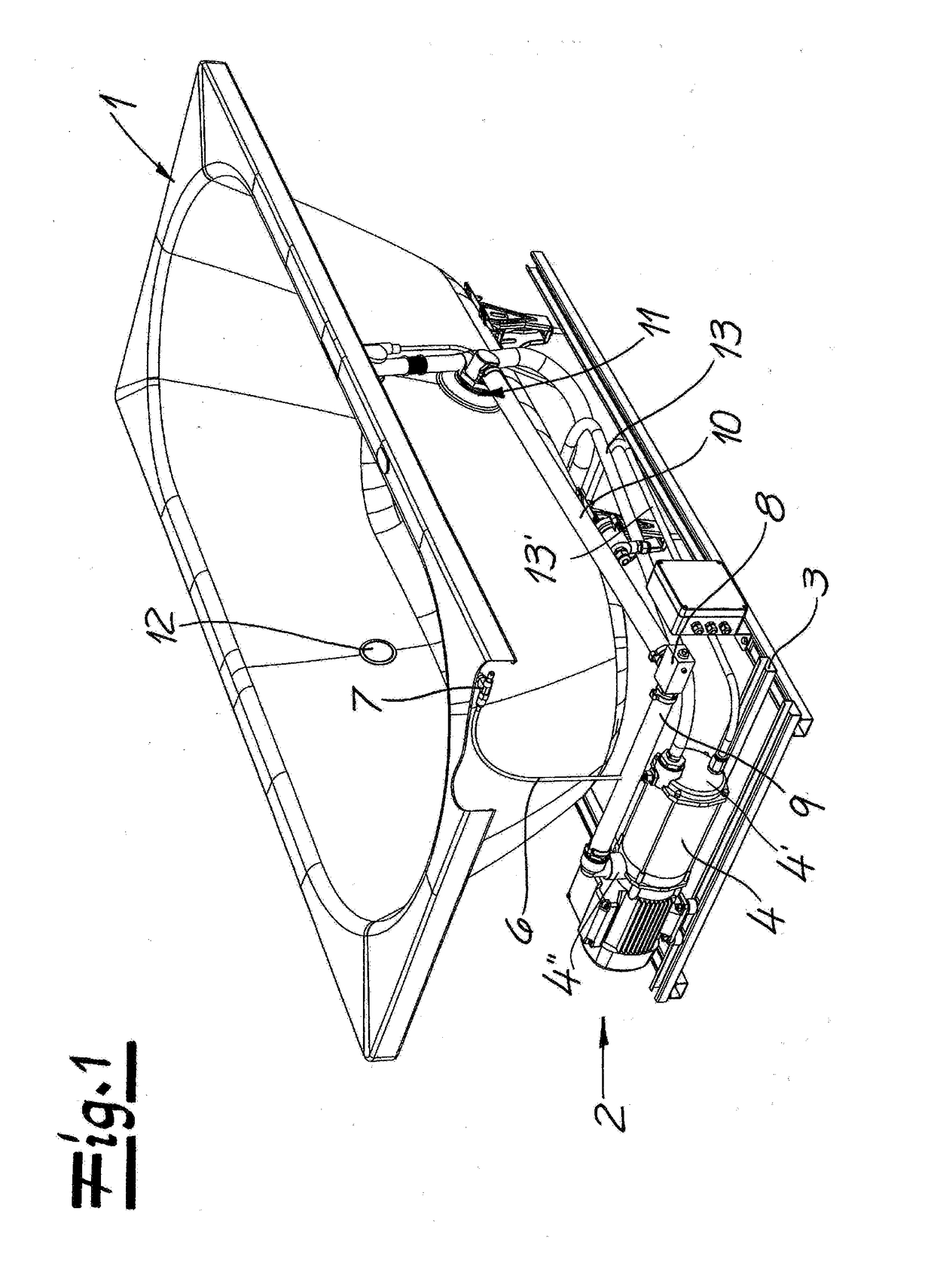
[0059]As seen in FIG. 1, a bathtub 1 sitting on a base 3 has a bathwater circulating system 2 that circulates bathwater through the bathtub 1. This bathwater is provided according to the invention with small bubbles in order to increase well-being for a user and achieve a positive influence on the skin of a user.

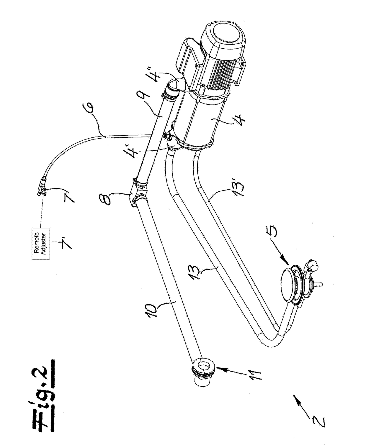
[0060]FIGS. 1 and 2 show how a centrifugal pump 4 having an intake port 4′ and an output port 4″ draws bathwater out of the tub 1 through a floor drain 5 connected to the intake port 4′. An air-supply conduit 6 having an intake valve 7 is also connected to the intake port 4′. An intake valve 7 at an upstream end of the air-supply conduit 6 is below an upper edge of the tub 1, and is preferably a needle valve that makes possible a precise dosing of the ambient air that is drawn in there. Preferably, the intake valve 7 can be adjusted directly by hand or with a tool, and it is normally protected by an inspection flap or a cover, or can also be mounted to be freely accessible. ...


PUM

PropertyMeasurementUnit
Pressureaaaaaaaaaa
Pressureaaaaaaaaaa
Pressureaaaaaaaaaa

Abstract

A bathwater circulating system has a pump operable to draw fluid in at an intake port and expel it under pressure at an output port. Water- and air-supply conduits feed water and air to the intake port at a rate determined by a flow-restricting air-intake valve so that the pump mixes the water and the air, pressurizes the mixture and thereby dissolves the air in the water, and expels the air / water mixture at the output port. A pressure-reducing valve is connected by an output conduit that extends from the output port to the pressure relief valve and conducts the water / air-bubble mixture from the pump to the pressure-reducing valve without separation of the air from the water and such that the mixture is at least partially depressurized at the pressure-reducing valve such that the air forms microbubbles in the water.

Description

FIELD OF THE INVENTION[0001]The present invention relates to a bathwater circulating system. More particularly this invention concerns a bathtub with such a system and to a method of operating the system.BACKGROUND OF THE INVENTION[0002]A typical bathwater circulating system for producing a mixture of water and air bubbles has a pump, an air-supply conduit provided with an inflow regulator, in particular an intake valve, and connected to a water-supply conduit that is in turn connected to an intake port of the pump having an output port connected to a pressure-reducing valve. This system is typically used with a bathing vessel that can for example be a bathtub, a seated bath, a foot bath or even a washbasin.[0003]The bathwater circulating system is provided for producing particularly fine bubbles that are barely perceptible to a user, which bubbles can accordingly also be called microbubbles.[0004]Thus the bathwater circulating system according to the invention thus differs from con...

Claims


Application Information

Patent Timeline
IPC IPC(8): B01F3/04F04D31/00B01F15/02F04D29/42B01F5/16B01F13/04F04D15/00F04D1/00B01F25/64B01F35/60
CPCB01F3/0451F04D15/0022F04D31/00F04D1/00F04D29/4293F04D29/4206B01F2003/04872B01F13/042B01F15/026B01F15/0292A61H33/0087B01F2215/0052B01F5/16A61H33/02B01F23/2323A47K3/02A47K3/10E03C1/01E03C1/02E03C1/021A47K3/00F04B13/00F04B49/065F04B53/1077F16K17/30A61H2033/0033A61H2033/0083A61H2033/022A61H2033/023A61H2201/50A61H2201/5082A61H33/026A61H33/027A61H33/6047A61H33/6057A61H33/6063A61H33/6073A61H2033/021B01J19/006B01J19/0066B01J19/18B01J19/1875B01J2219/00081B01J2219/00779C08G63/08B01F25/53B01F27/0726B01F27/191B01F27/861B01F27/86B01F27/906B01F35/718B01F35/93B01F23/23231B01F25/64B01F35/602B01F35/7547B01F35/71805B01F23/237611B01F2101/305
Inventor SCHMIDT, THOMASMEYER, TOBIAS
Owner FRANZ KALDEWEI
Why Eureka
Eureka Blog
Learn More