Waste Management

a technology of waste management and waste, applied in the direction of steam superheaters, dynamo-electric machines, steam generation using hot heat carriers, etc., can solve the problems of low efficiency of turbines driven by low temperature, increased maintenance and shutdown time, and reduced heat recovery efficiency and overall plant efficiency

Inactive Publication Date: 2017-05-04
CHINOOK END STAGE RECYCLING
View PDF11 Cites 2 Cited by
  • Summary
  • Abstract
  • Description
  • Claims
  • Application Information

AI Technical Summary

Benefits of technology

[0015]It may be convenient to maintaining the first temperature of the steam obtained in step (a) at or below a predetermined threshold. This helps to minimize corrosion of the equipment by contaminants present in the waste gas. Thus, in some embodiments, the method comprises monitoring the first temperature and / or the pressure of the steam obtained in step (a). In some embodiments, the method further comprises controlling the first temperature and / or pressure of the steam obtained in step (a). The pressure of the steam may be controlled by, for example, controlling the pressure of the water supply. The first temperature of the steam may be controlled by restricting the quantity and / or temperature of the waste gas passed through the first boiler.
[0062]It may also be useful to monitor the temperature of the gases in the system. For example, a temperature sensor may be provided for monitoring the temperature of gas released by the gas outlet of the first boiler to ensure that the gas has been cooled sufficiently to avoid or minimize corrosion by contaminants present in the gas.

Problems solved by technology

The corrosive nature of the waste gas imposes significant challenges for heat recovery, since it shortens the lifetime of heat exchangers, increases the frequency of maintenance and shut-down time, and limits the heat recovery efficiency and overall plant efficiency.
A consequence of this, however, is the low efficiency of turbines driven by low temperature, low pressure steam.
This not only makes the heat recovery equipment inefficient, but also decreases the total plant output, and makes waste-to-energy projects less economically viable.

Method used


Image

  • Waste Management
  • Waste Management

Examples


Embodiment Construction

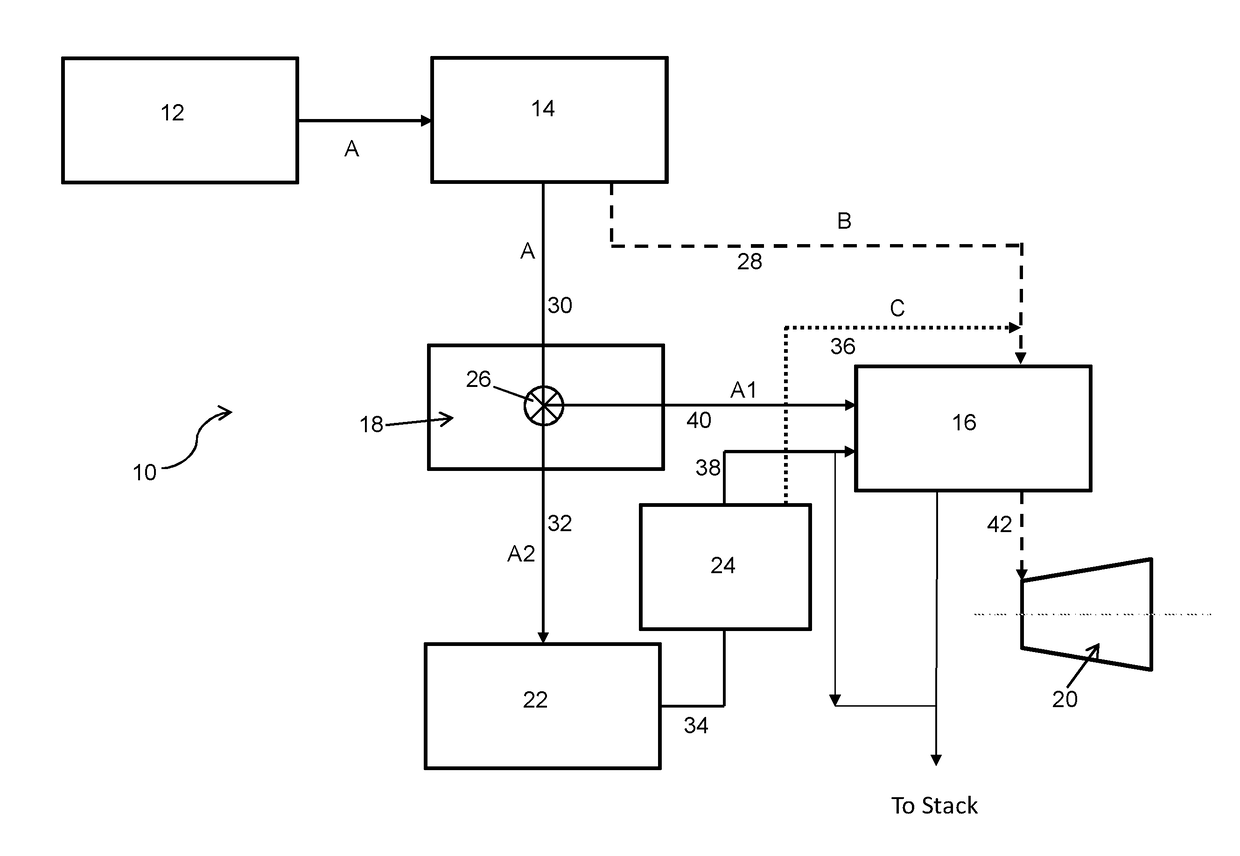
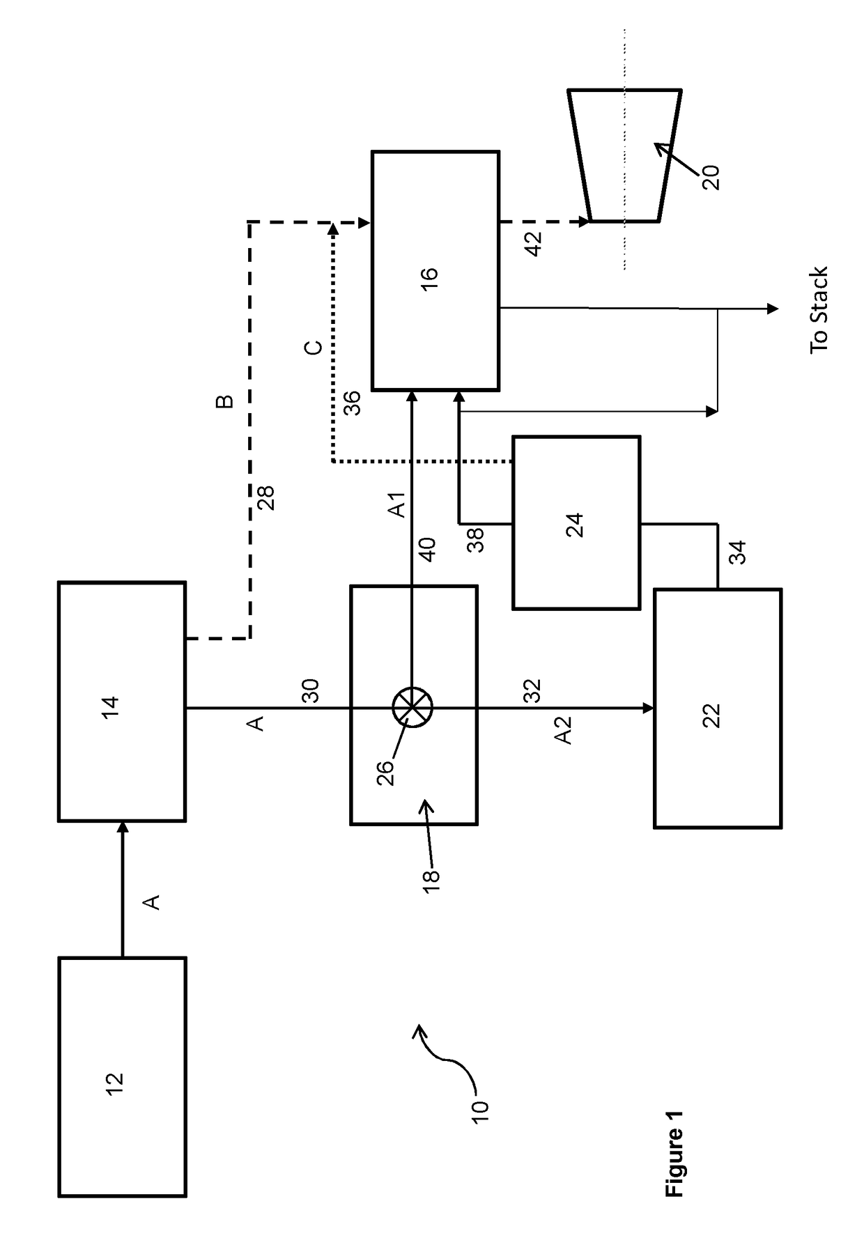
[0064]Embodiments of the invention will now be described with reference to the accompanying Figure in which is a schematic diagram of a waste gas management system in accordance with an embodiment of the present invention.

[0065]With reference to FIG. 1, a waste gas management system 10 comprises a gasification or pyrolysis unit 12, a first heat recovery boiler 14, a second boiler 16, a cleaning apparatus 18, and a steam turbine 20. The system 10 additionally comprises a power generation plant 22 and a third boiler 24, all being connected by conduits defining the various flowpaths.

[0066]A first flow path A for the transfer of gas is provided from the gasification unit 12, through the first boiler 14 and on to the cleaning apparatus 18. At this point the flow path A branches into a first branch A1, which leads directly to the second boiler 16, and a second branch A2 which leads to the second boiler 16 via the power generation plant 22 and the third boiler 24. A computer controlled val...


PUM


Abstract

The present invention relates to a method for producing steam, the method comprising: (a) passing waste gas through a first boiler to produce steam having a first temperature, and cooled waste gas; (b) removing contaminants from the cooled waste gas to produce clean waste gas; (c) passing the steam having a first temperature through a second boiler; and (d) burning at least a portion of the clean waste gas in the second boiler to produce steam having a second temperature, the second temperature being higher than the first temperature. The method is particularly suited to efficiently generating high temperature, high pressure steam derived from the pyrolysis / gasification of organic waste.

Description

[0001]The present invention relates to the production of steam from waste gas, more particularly to a method and a system for producing high temperature, high pressure steam from waste gas.BACKGROUND TO THE INVENTION[0002]Waste gases are produced by the pyrolysis or gasification of industrial or municipal solid waste. It is desirable to recover both the chemical energy and the heat energy present in the waste gas to maximize energy efficiency.[0003]The corrosive nature of the waste gas imposes significant challenges for heat recovery, since it shortens the lifetime of heat exchangers, increases the frequency of maintenance and shut-down time, and limits the heat recovery efficiency and overall plant efficiency. To minimize degradation of the heat exchangers caused by the corrosive gases, the temperature within heat recovery boilers is restricted. High pressures are also conventionally avoided in order to minimize the stresses placed on the pipes.[0004]In order to maintain reliabilit...

Claims


Application Information

Patent Timeline
Patent Type & Authority Applications(United States)
IPC IPC(8): F01K23/06H02K7/18F01K13/00F01K25/14F01K13/02
CPCF01K23/067F01K25/14H02K7/1815F01K13/003H02K7/1823F01K13/02Y02E20/18F01K3/18F01K3/24F22B1/18F22B1/1892F22B33/00F22G1/00
Inventor CHALABI, RIFAT ALPERRY, OPHNEIL HENRYLI, KE
Owner CHINOOK END STAGE RECYCLING
Why Eureka
Try Eureka