
Film structure and its measuring method, display substrate and its measuring method and manufacturing method

a film structure and measuring method technology, applied in the field of display, can solve the problems of inaccurate value of the dielectric constant of the film, adversely affecting the accuracy of the thickness value of the film obtained by the measurement,

Active Publication Date: 2017-05-04
BOE TECH GRP CO LTD
View PDF6 Cites 0 Cited by
  • Summary
  • Abstract
  • Description
  • Claims
  • Application Information

AI Technical Summary

Benefits of technology

The present invention provides accurate methods for measuring the thickness and dielectric constant of an insulation layer in a film structure, by measuring the fall of a step structure through the motion trajectory of a measuring probe at the time of ascending or descending. This is a more accurate measurement than estimating the thickness of the film by chemical vapor deposition or using a scanning electron microscope. The insulation layer is made of three layers including a first metal layer, an insulation layer, and a second metal layer. The method can be used in the manufacturing process of a display substrate.

Problems solved by technology

However, an accuracy of the thickness values of the film obtained by the measurements is adversely affected to a certain degree because it is limited to the fact that it cannot be ensured that a slice is completely perpendicular to the film when preparing a sample, and that the slice to be measured is also probably an inclined plane during measurement of the sample.
As a result, a value of the dielectric constant of the film which is finally found is not accurate.

Method used


Image

  • Film structure and its measuring method, display substrate and its measuring method and manufacturing method
  • Film structure and its measuring method, display substrate and its measuring method and manufacturing method
  • Film structure and its measuring method, display substrate and its measuring method and manufacturing method

Examples


Embodiment Construction

[0018]Specific embodiments of a film structure and its measuring method, a display substrate and its measuring method and manufacturing method will be described in detail as below with reference to the accompanying drawings.

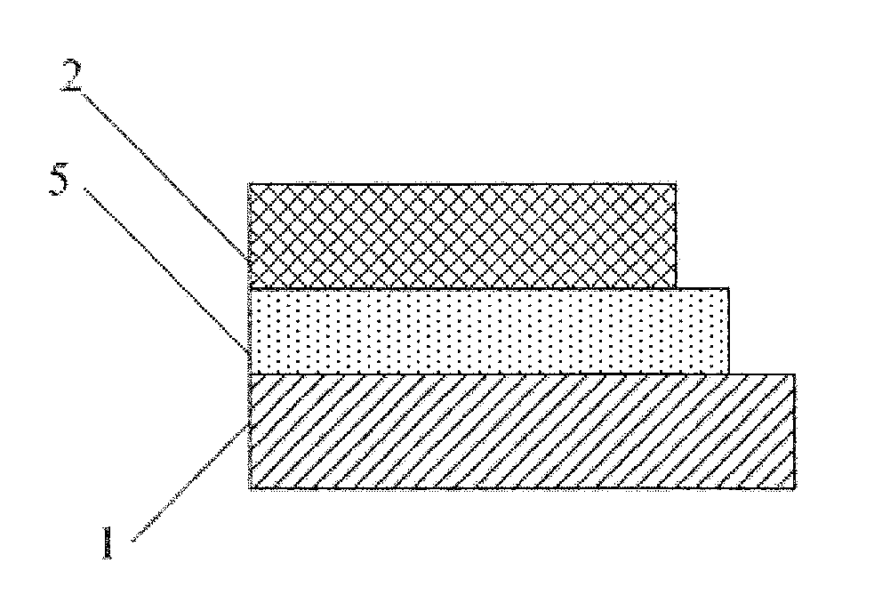
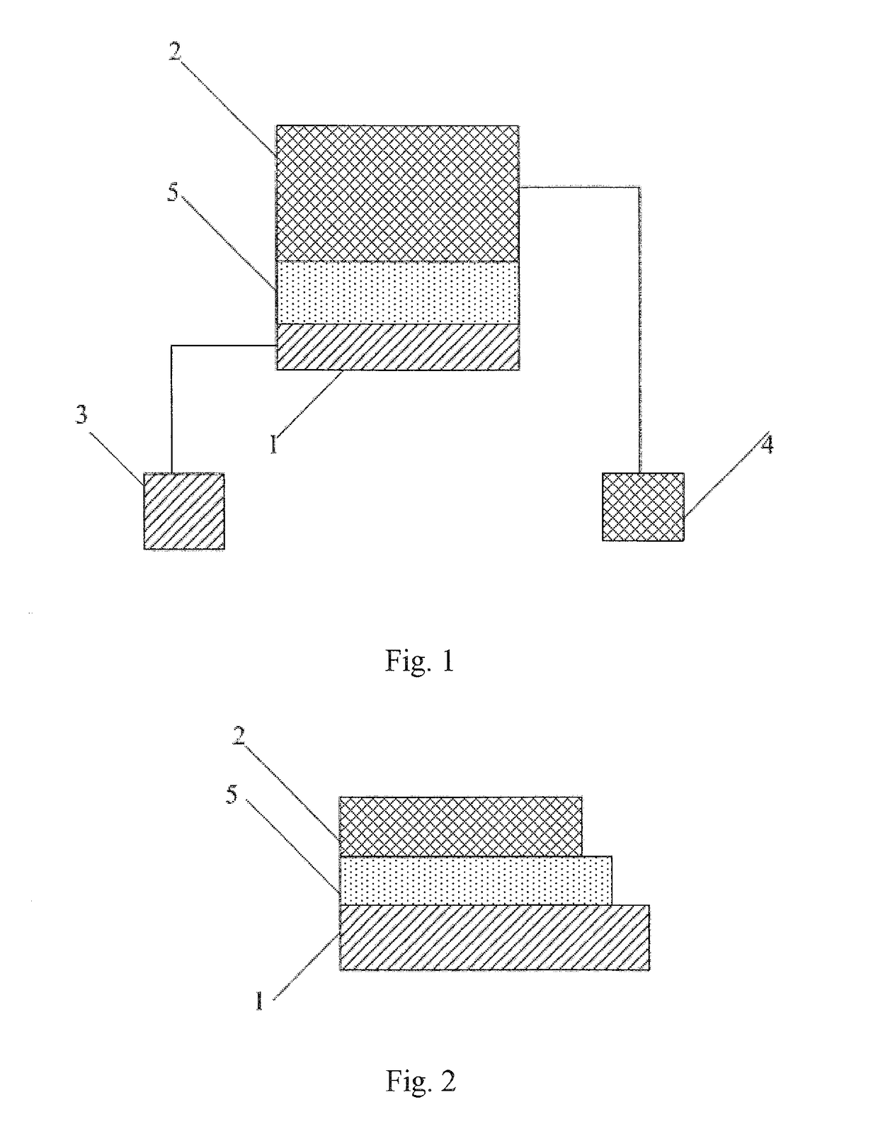
[0019]Embodiments of the present invention provide a film structure. As shown in FIGS. 1 and 2, the film structure comprises: a first metal layer 1, a second metal layer 2, a first measuring terminal 3, a second measuring terminal 4, and an insulation layer 5 located between the first metal layer 1 and the second metal layer 2.

[0020]The first measuring terminal 3 is connected with the first metal layer 1, and the second measuring terminal 4 is connected with the second metal layer 2.

[0021]In at least a portion of an edge region of the film structure, the first metal layer 1 extends outwards relative to an edge of the insulation layer 5 by a first predetermined length, and the insulation layer 5 extends outwards relative to an edge of the second metal layer 2 by a...


PUM

PropertyMeasurementUnit
lengthaaaaaaaaaa
structureaaaaaaaaaa
areaaaaaaaaaaa

Abstract

A film structure includes a first metal layer, a second metal layer, and an insulation layer located between the first metal layer and the second metal layer. In at least a portion of an edge region of the film structure, the first metal layer extends outwards relative to an edge of the insulation layer by a first predetermined length, and the insulation layer extends outwards relative to an edge of the second metal layer by a second predetermined length. In this way, when the film structure is measured, a fall value between the surface, adjacent to the second metal layer, of the insulation layer and the surface, adjacent to the insulation layer, of the first metal layer is measured by means of a motion trajectory of the measuring probe at the time of ascending or descending, thereby obtaining a more accurate thickness value of the insulation layer.

Description

CROSS-REFERENCE TO RELATED APPLICATIONS[0001]This application is a Section 371 National Stage Application of International Application No. PCT / CN2015 / 089944, filed on 18 Sep. 2015, entitled “FILM STRUCTURE AND ITS MEASURING METHOD, DISPLAY SUBSTRATE AND ITS MEASURING METHOD AND MANUFACTURING METHOD”, which has not yet published, which claims priority to Chinese Application No. 201510214085.8, filed on 29 Apr. 2015, incorporated herein by reference in their entirety.BACKGROUND[0002]1. Technical Field[0003]Embodiments of the present invention relate to the field of display, and particularly to a film structure and its measuring method, a display substrate and its measuring method and manufacturing method.[0004]2. Description of the Related Art[0005]Measurement of a dielectric constant of a film to be measured, generally, is necessary to be performed on a display substrate for achieving a displaying function. A conventional measurement of dielectric constant is performed as follows. Fi...

Claims


Application Information

Patent Timeline
Patent Type & Authority Applications(United States)
IPC IPC(8): G01R27/26
CPCG01R27/2617G02F1/1309G01D5/24G01R27/2605G01D5/2405
Inventor ZHANG, YUJUNLIU, CHAO
Owner BOE TECH GRP CO LTD
Learn More