Broadband multiple layer dielectric resonator antenna and method of making the same

a dielectric resonator antenna and multiple layer technology, applied in the direction of additive manufacturing process, protective material radiating element, manufacturing tool, etc., can solve the problems of limited bandwidth, limited efficiency, limited gain,

Active Publication Date: 2017-05-04
ROGERS CORP
View PDF1 Cites 58 Cited by
  • Summary
  • Abstract
  • Description
  • Claims
  • Application Information

AI Technical Summary

Benefits of technology

[0005]An embodiment includes a dielectric resonator antenna (DRA) having: an electrically conductive ground structure; a plurality of volumes of dielectric materials disposed on the ground structure having N volumes, N being an integer equal to or greater than 3, disposed to form successive and sequential layered volumes V(i), i being an integer from 1 to N, wherein vo

Problems solved by technology

Existing resonators and arrays employ patch antennas, and while such antennas may be suitable for their intended purpose, they also have drawbacks, such as limited bandwidth, limited efficiency, and therefore limited gain.
Techniques that have been employed to improve the bandwidth have typically led to expensive and complicated multilayer and multi-patch designs, and it remains challenging to achieve bandwid

Method used


Image

  • Broadband multiple layer dielectric resonator antenna and method of making the same
  • Broadband multiple layer dielectric resonator antenna and method of making the same
  • Broadband multiple layer dielectric resonator antenna and method of making the same

Examples


embodiment-2

[0259] The DRA of Embodiment-1, wherein each successive volume V(i+1) forms a layered shell disposed over and completely 100% embedding volume V(i).

embodiment-3

[0260] The DRA according to any preceding Embodiment, wherein volume V(N) completely 100% embeds all volumes V(1) to V(N−1).

[0261]Embodiment-4: The DRA according to any preceding Embodiment, wherein the signal feed is disposed within an opening of the ground structure in non-electrical contact with the ground structure, and is disposed within one of the plurality of volumes of dielectric materials.

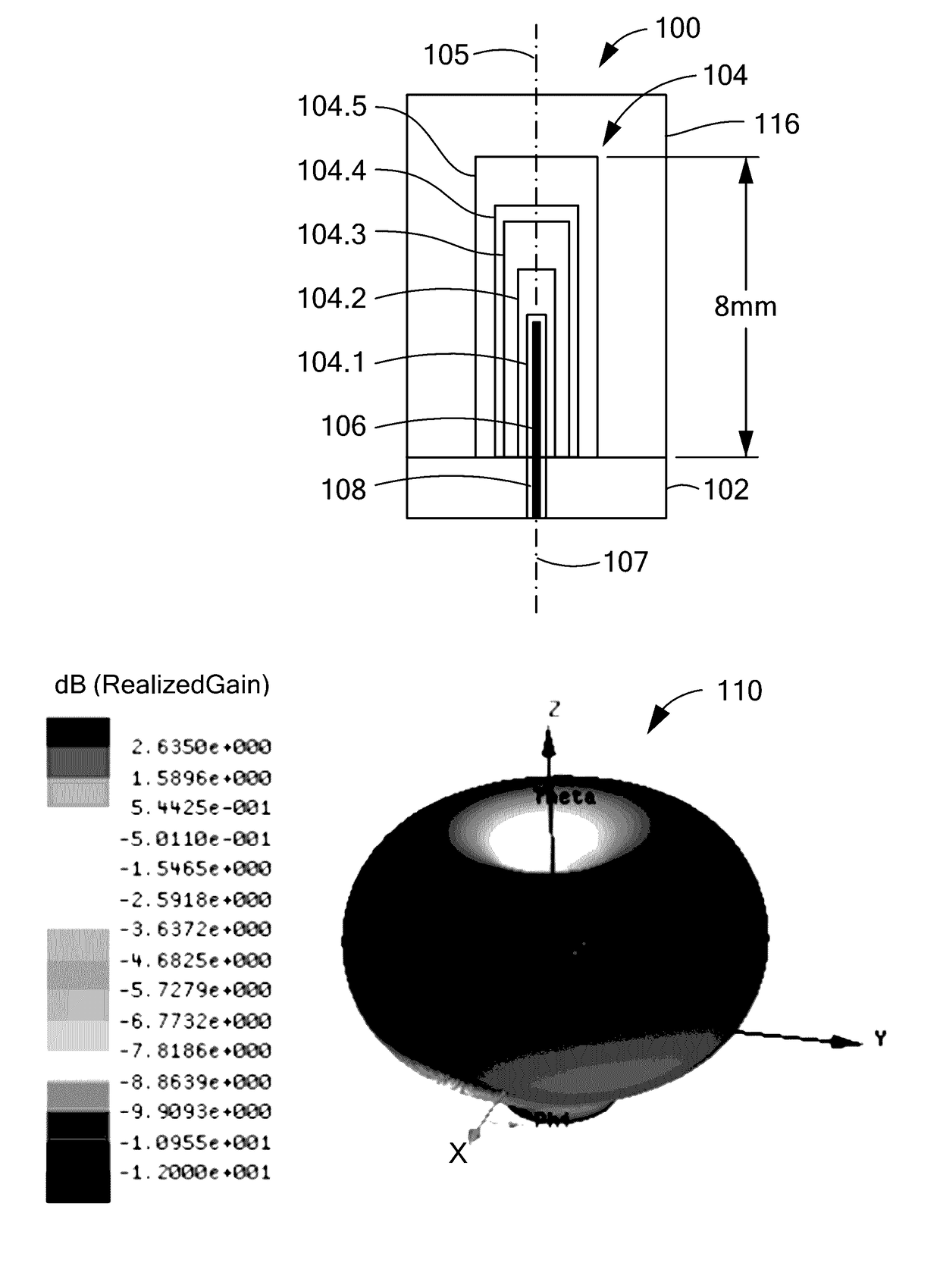
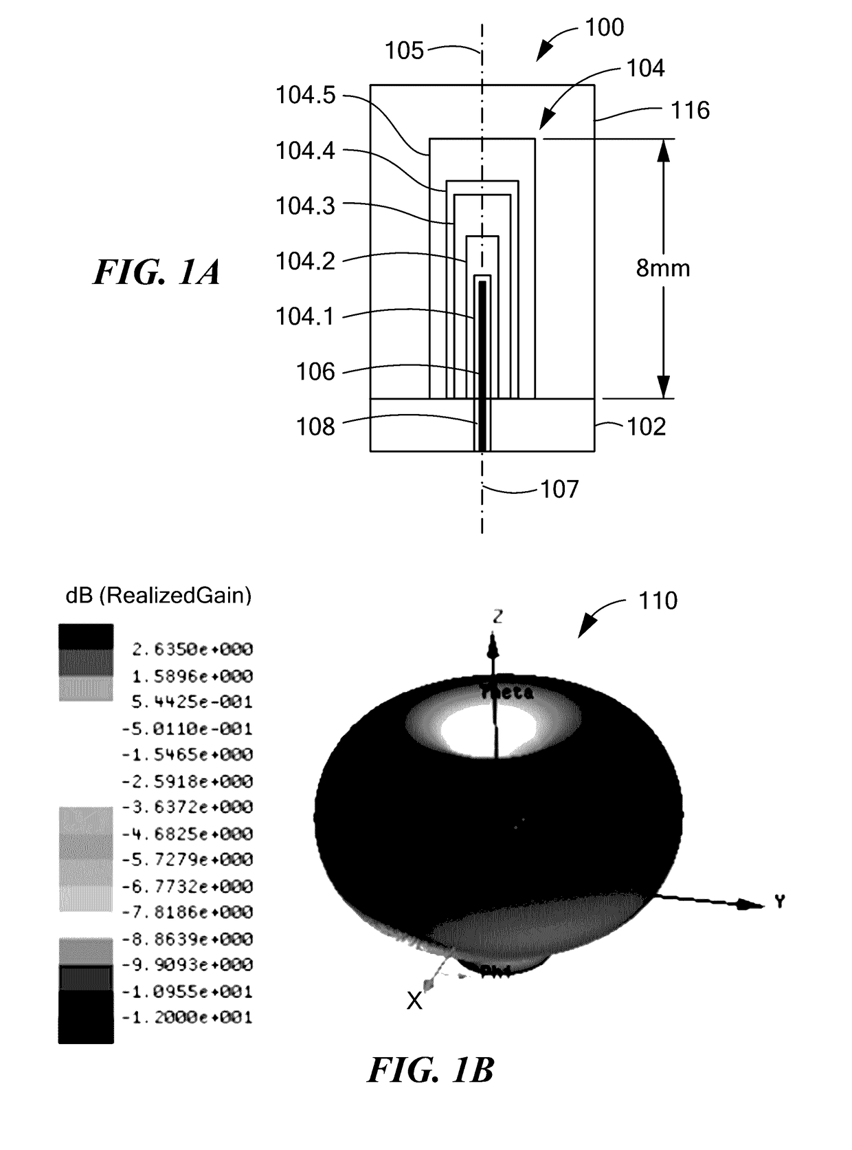
[0262]Embodiment-5: The DRA according to any preceding Embodiment, wherein: the DRA when excited by an electrical signal on the signal feed is configured to produce a far field 3D radiation pattern that occupies a topological space corresponding to a single element homotopy group defined by a family of closed loop paths that are each contractible at a single point within the 3D radiation pattern.

[0263]Embodiment-6: The DRA according to any preceding Embodiment, wherein: the DRA when excited by an electrical signal on the signal feed is configured to produce a far field 3D radiation pattern...

embodiment-7

[0264] The DRA according to any preceding Embodiment, wherein: each layered volume of the plurality of volumes of dielectric materials has a dielectric constant 6(i), wherein the dielectric constant and the volume of each respective layer are in accordance with the following relationship: ε(i+1)*V(i+1)≈ε(i)*V(i); except for ε(1)*V(1), where ε(1)≈the dielectric constant of air.

[0265]Embodiment-8: The DRA according to any preceding Embodiment, wherein: each layered volume of the plurality of volumes of dielectric materials has a dielectric constant 6(i), wherein the dielectric constant and the volume of each respective layer are in accordance with the following relationship: ε(i)*V(i)≈C(f); where C(f) is a constant at a given frequency; except for ε(1)*V(1), where ε(1)≈the dielectric constant of air.

[0266]Embodiment-9: A dielectric resonator antenna (DRA), having: a plurality of volumes of dielectric materials having N volumes, N being an integer equal to or greater than 3, disposed t...


PUM

PropertyMeasurementUnit
Fractionaaaaaaaaaa
Volumeaaaaaaaaaa
Electrical conductoraaaaaaaaaa

Abstract

A dielectric resonator antenna (DRA) includes: an electrically conductive ground structure; a plurality of volumes of dielectric materials disposed on the ground structure comprising N volumes, N being an integer equal to or greater than 3, disposed to form successive and sequential layered volumes V(i), i being an integer from 1 to N, wherein volume V(1) forms an innermost volume, wherein a successive volume V(i+1) forms a layered shell disposed over and at least partially embedding volume V(i), wherein volume V(N) at least partially embeds all volumes V(1) to V(N−1); and a signal feed disposed and structured to be electromagnetically coupled to one or more of the plurality of volumes of dielectric materials.

Description

CROSS REFERENCE TO RELATED APPLICATIONS[0001]This application claims the benefit of priority of: U.S. Provisional Application Ser. No. 62 / 247,459, filed Oct. 28, 2015; U.S. Provisional Application Ser. No. 62 / 258,029, filed Nov. 20, 2015; and, U.S. Provisional Application Ser. No. 62 / 362,210, filed Jul. 14, 2016, all of which are incorporated herein by reference in their entireties.BACKGROUND OF THE INVENTION[0002]The present disclosure relates generally to a dielectric resonator antenna (DRA), particularly to a multiple layer DRA, and more particularly to a broadband multiple layer DRA for microwave and millimeter wave applications.[0003]Existing resonators and arrays employ patch antennas, and while such antennas may be suitable for their intended purpose, they also have drawbacks, such as limited bandwidth, limited efficiency, and therefore limited gain. Techniques that have been employed to improve the bandwidth have typically led to expensive and complicated multilayer and mult...

Claims


Application Information

Patent Timeline
IPC IPC(8): H01Q9/04H01Q1/36H01Q1/42H01Q1/48H01Q5/50
CPCH01Q9/0485H01Q1/48H01Q1/36H01Q1/422H01Q5/50H01Q21/061H01Q5/364H01Q1/523H01Q1/40H01Q9/0492H01Q21/30H01Q1/38H01Q9/0457B29C64/147B29C64/153B29C64/112B29C64/118B29C64/10B33Y10/00
Inventor PANCE, KRISTISPRENTALL, KARLWILLIAMS, SHAWN P.
Owner ROGERS CORP
Why Eureka
Try Eureka