
A Method Of Analyzing An Object In Two Stages Using A Transmission Spectrum Then A Scattering Spectrum

a technology of transmission spectrum and scattering spectrum, applied in the field of diffractometry, can solve the problems of inability to use monochrome sources for imaging on account of their bulk, inability to analyze objects in two stages, and inability to use monochrome sources for imaging, etc., to achieve the effect of reducing the drawbacks, speeding up the effect and improving the

Active Publication Date: 2017-05-11
COMMISSARIAT A LENERGIE ATOMIQUE ET AUX ENERGIES ALTERNATIVES
View PDF2 Cites 10 Cited by
  • Summary
  • Abstract
  • Description
  • Claims
  • Application Information

AI Technical Summary

Benefits of technology

This patent is about a way to analyze objects faster and better. It aims to fix the problems with current methods.

Problems solved by technology

This short-range order causes intramolecular and intermolecular interferences.
Although these devices are very accurate, they require the use of a powerful monochrome source and cannot be used for imaging on account of their bulk.
However, this type of detector must be cooled to very low temperatures, by complex and / or costly methods (thermoelectric cooling or cooling by a tank of liquid nitrogen).
Also, the analysis devices employing such a detector are very bulky.
However, their performance in terms of energy resolution is still less than that obtained with the Germanium detectors, even though quite good.
It is known that the identification of a material by the production then analysis of a scattering spectrum may be painstaking when it is wished to characterize objects of high volume.
The length of execution of the method of WO 2006 / 075296 makes it incompatible with certain applications such as the search for explosive or dangerous products in baggage.

Method used


Image

  • A Method Of Analyzing An Object In Two Stages Using A Transmission Spectrum Then A Scattering Spectrum
  • A Method Of Analyzing An Object In Two Stages Using A Transmission Spectrum Then A Scattering Spectrum
  • A Method Of Analyzing An Object In Two Stages Using A Transmission Spectrum Then A Scattering Spectrum

Examples


Embodiment Construction

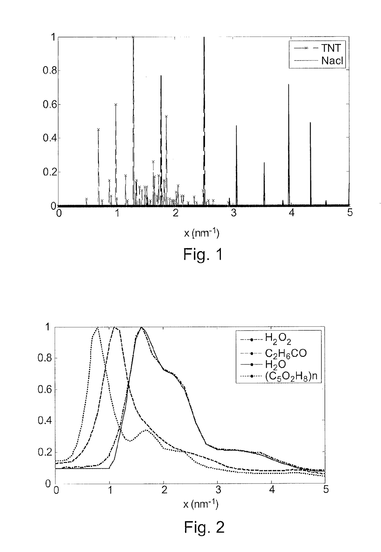
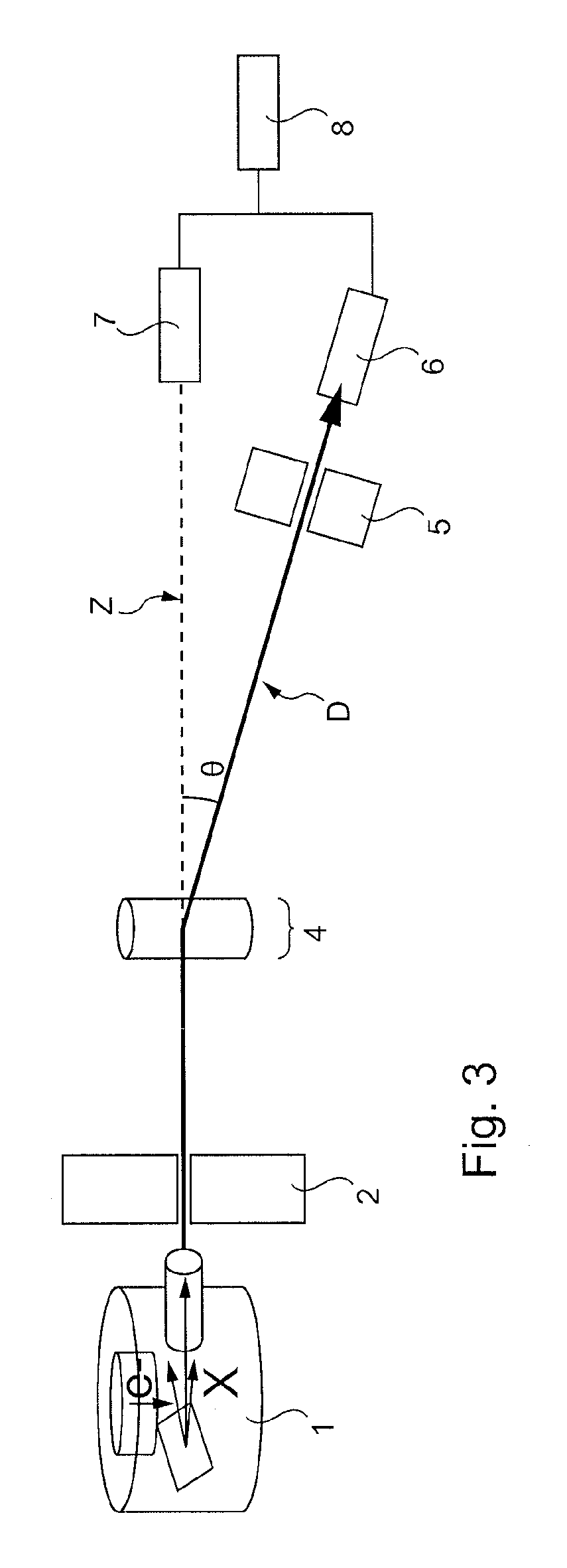
[0110]The detection system according to the invention illustrated in FIG. 3 comprises:[0111]a polychromatic source 1 of ionizing radiation, such as an X-ray tube,[0112]a source collimator 2, which makes it possible to channel the radiation from source 1 into an incident beam of central axis Z,[0113]a receiving zone 4 for an object to analyze;[0114]a scattering collimator 5 having a collimation axis D,[0115]a spectrometric detector 6 placed for scattering, which is associated with the scattering collimator 5 such that the detector 6 detects a radiation scattered at a scattering angle θ (angle between the incident axis Z and the axis of collimation and detection D) for example equal to 2.5 (the representation in FIG. 3 not being to scale); the spectrometric detector 6 placed for scattering is configured to establish a measured scattering spectrum (of energy), that is to say an energy spectrum of the radiation scattered by the object in the direction D; the spectrometric detector 6 is,...


PUM


Abstract

A method for analyzing an object, includes irradiating the object with incident photon radiation, acquiring a spectrum transmitted by the object using a spectrometric transmission detector, determining at least one first property of the object from the transmission spectrum, verifying that at least one doubt criterion relating to the first property of the object is met, and translating the fact that the object contains a material that is potentially dubious for the application under consideration. A second part, carried out only when the doubt criterion is met, includes acquiring an energy spectrum scattered by the object using a spectrometric scattering detector at an angle of 1° to 15°, and determining a second property of the object from at least the scatter spectrum and comparing at least the second property of the object with properties of standard materials stored in a database to identify the objects composition material.

Description

RELATED APPLICATIONS[0001]This application is a Section 371 nationalization of PCT application No. PCT / FR2015 / 051713, filed Jun. 25, 2015, the entire contents of which are incorporated by reference herein.TECHNICAL FIELD[0002]The present invention concerns a method of analyzing an object by diffractometry, and an associated detection system.BACKGROUND[0003]Diffractometry relates to the irradiation of a material or object using a source of electromagnetic radiation, of X or gamma type, followed by the analysis of radiation from elastic scattering at a small angle. The expression “radiation from elastic scattering at a small angle” designates the radiation coherently scattered by the material or object at an angle less than 15°, or less even than 10°, relative to the direction of the radiation that is incident on the material or object. As a matter of fact, beyond 10°, elastic scattering, or Rayleigh scattering, becomes progressively negligible. It is known to use diffractometry to de...

Claims


Application Information

Patent Timeline
IPC IPC(8): G01N23/20G01N23/087G01N23/201
CPCG01N23/20083G01N23/201G01N23/087G01N2223/50G01N2223/045G01N2223/054G01N2223/03G01N2223/304G01N23/207G01N2223/04
Inventor PAULUS, CAROLINETABARY, JOACHIM
Owner COMMISSARIAT A LENERGIE ATOMIQUE ET AUX ENERGIES ALTERNATIVES
Learn More