Supercharge Your Innovation With Domain-Expert AI Agents!

Solid electrolytic condenser and method of manufacturing the same

a technology of solid electrolyte and condenser, which is applied in the manufacture of electrolytic capacitors, capacitor dielectric layers, electrolytic capacitors, etc., can solve the problems of increased packaging size, reduced manufacturing efficiency, deficient welding and welding strength degradation, etc., to reduce the number of welding processes, and eliminate the effect of problems associated

Active Publication Date: 2017-05-11
ROHM CO LTD
View PDF7 Cites 1 Cited by
  • Summary
  • Abstract
  • Description
  • Claims
  • Application Information

AI Technical Summary

Benefits of technology

The present invention relates to a solid electrolyte condenser that has a spacer, which is made of conductive material and connected to the anode wires of the capacitor component at both ends in a thickness direction. The spacer is fixed to the anode connection portion using one welding process, which reduces the number of welding processes and increases the efficiency of manufacturing. This results in decreased ESR (equivalent series resistance) and improved welding strength, addressing issues associated with deficient welding and increasing manufacturing efficiency.

Problems solved by technology

Such configuration of the condenser component may result in the increased size of the package.
Therefore, the increased amount of welding reduces manufacturing efficiency.
Welding spots in close proximity to one another also causes deficient welding and welding strength degradation.
Moreover, according to Patent Literature 2, regarding the two alternative processes of forming the pair of spacers and the anode terminal as a whole, or omitting the spacer and shaping the front end portion of the anode terminal as a spacer, either option involves a complicated bending process, which is problematic.

Method used


Image

  • Solid electrolytic condenser and method of manufacturing the same
  • Solid electrolytic condenser and method of manufacturing the same
  • Solid electrolytic condenser and method of manufacturing the same

Examples


Embodiment Construction

[0057]Embodiments for implementing the present invention (hereinafter, the embodiments) are specifically discussed below by referencing to the drawings.

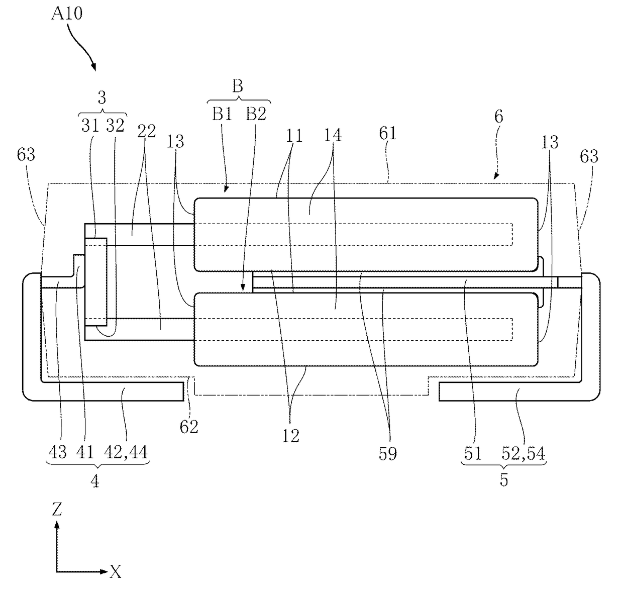
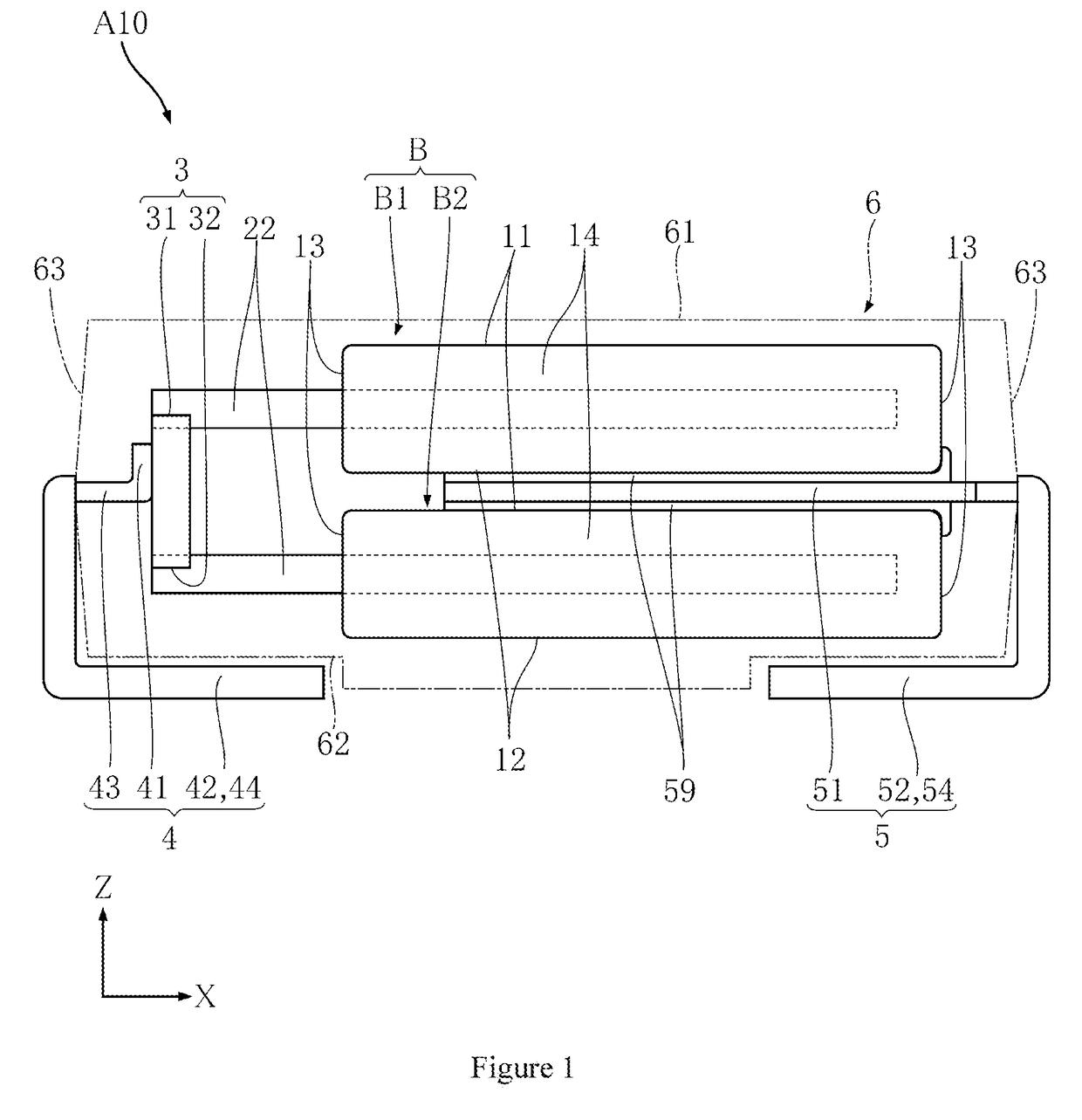
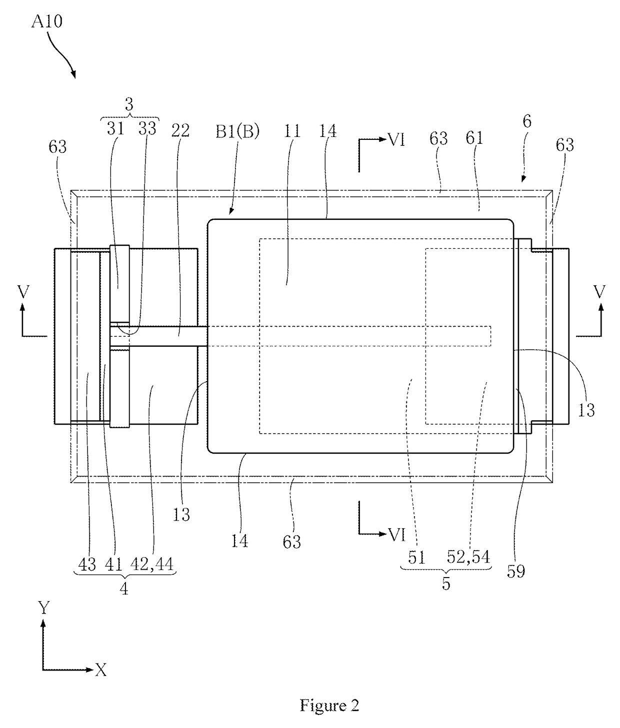
[0058]Embodiments of the solid electrolyte condenser A10 according to the present invention are discussed by referencing FIGS. 1 to 8. The solid electrolyte condenser A10 has two condenser components B, a spacer 3, an anode terminal 4, a cathode terminal 5, a conductive adhesion layer 59, and a sealing resin 6.

[0059]FIG. 1 is the right side view of the solid electrolyte condenser A10. FIG. 2 is the top view of the solid electrolyte condenser A10. FIG. 3 is a front view of the solid electrolyte condenser A10. FIG. 4 is a bottom view of the solid electrolyte condenser A10. FIG. 5 is a cross-sectional view along line V-V in FIG. 2. FIG. 6 is a cross-sectional view along line VI-VI in FIG. 2. FIG. 7 is a partial enlargement view illustrating the condenser component B of the solid electrolyte condenser A10. FIG. 8 is a three dimensional v...


PUM


Abstract

A solid electrolyte condenser includes two condenser components disposed along a first direction Z and connected in parallel. Each condenser component includes: a porous sintered body forming an anode; an anode wire having a portion being inserted into the porous sintered body; a dielectric layer covering the porous sintered body; and a cathode portion forming a cathode. The solid electrolyte condenser includes: a spacer, which is conductive and of which two ends in the first direction Z are respectively connected with the anode wires; an anode terminal, fixed to a side of the spacer that is opposite to the two condenser components; a cathode terminal, connected with each cathode portion at the two sides in the first direction Z; a sealing resin, covering the two condenser components; and an anode connection portion, fixed at the anode terminal of the spacer and formed along the first direction Z.

Description

TECHNICAL FIELD[0001]The present invention is related to, in particular, solid electrolyte condensers having a condenser component that comprises an anode having a sintered body with a valve metal and is encased in a surface mounted resin package and methods of manufacturing the same.valve metalvalve metalBACKGROUND[0002]With the development in the miniaturization and complex functionality of electronic devices in recent years, the power supplied to the electronic devices shall be operated in the high-frequency area. Accordingly, noise control and source-voltage smoothing are required, and consequently, the functions performed by the capacitor in the electronic circuit are becoming more and more important in electronic componentry. There is a high demand for solid electrolyte condensers that are more compact and have greater electrostatic capacitance and excellent frequency characteristics providing low impedance.[0003]Generally, the impedance of a condenser in a low frequency range...

Claims


Application Information

Patent Timeline
IPC IPC(8): H01G9/26H01G9/052H01G9/025H01G9/10H01G9/07H01G9/00H01G9/02H01G9/15H01G9/042
CPCH01G9/26H01G9/15H01G9/052H01G9/025H01G9/10H01G9/07H01G9/0029H01G9/02H01G9/042H01G9/012
Inventor NODA, MASAHIROMIURA, TAKESHI
Owner ROHM CO LTD
Features
  • R&D
  • Intellectual Property
  • Life Sciences
  • Materials
  • Tech Scout
  • Unparalleled Data Quality
  • Higher Quality Content
  • 60% Fewer Hallucinations
Learn More