Light-based measurement system and a method of collagen denaturation measurement and a skin treatment system

Active Publication Date: 2017-05-18
KONINKLJIJKE PHILIPS NV
View PDF1 Cites 0 Cited by
  • Summary
  • Abstract
  • Description
  • Claims
  • Application Information

AI Technical Summary

Benefits of technology

[0011]It is an object of the invention to provide a light-based measurement system for measuring collage

Problems solved by technology

The desire to maintain a youthful appearance by reducing wrinkles in the skin is an important issue in human society.
However, such home-use systems raise new concerns, such as concerns relating to safety and treatment efficacy.
This is particularly important when the light source for performing the treatment is a laser, and incorrect operation of such a laser can result in scarring or burning of the skin at locations where the laser light passes through the skin layers.
Damage to the epidermis, for example, is highly undesirable because this may lead to complications and health risks to the person being treated, as well as social downtime.
If superficial lesions are created above the dermis, petechiae (micro-bleeding) may occur due to micro-rupturing of capillaries, resulting in reduced efficacy and an increase in side effects.
The efficacy of a thermal treatment for collagen denaturation, and the subsequent collagen remodeling, are high only if the temperature insi

Method used


Image

  • Light-based measurement system and a method of collagen denaturation measurement and a skin treatment system
  • Light-based measurement system and a method of collagen denaturation measurement and a skin treatment system
  • Light-based measurement system and a method of collagen denaturation measurement and a skin treatment system

Examples


Embodiment Construction

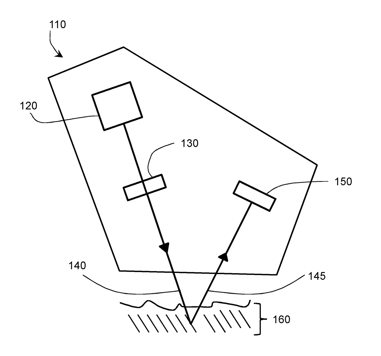
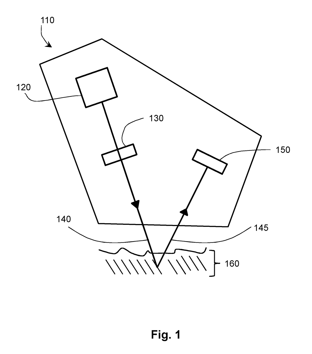
[0039]FIG. 1 schematically shows a skin measurement system 110 according to the invention. The measurement system 110 is configured and arranged for performing light-based measurement of collagen denaturation inside the skin 160. The measurement system 110 comprises a light source 120 for emitting light via a polarization modulator 130 to a target position inside the skin 160. The light source 120 is preferably a monochromatic source, such as laser or laser diode. A light source 120 with a narrow wavelength range may also be used.

[0040]The polarization modulator 130 is configured and arranged to receive, in use, the light beam emitted by the light source 120, and to spatially modulate a polarization direction of the light beam emitted by the light source, thereby generating a spatially modulated light beam having a spatially modulated polarization direction in a cross-section of the light beam extending perpendicularly to a propagation direction of the light beam. Thus, the polariza...


PUM


Abstract

The measurement system 110 comprises a light source 120 configured and arranged for emitting a light beam via a polarization modulator 130 to a target position inside the skin 160, wherein the polarization modulator 130 is configured and arranged to simultaneously provide, in use, a first and a second region in a cross-section of the light beam in the target position, the first and the second region being distinct and having a corresponding first and second direction of polarization, the first and the second polarization direction being different from each other, and the measurement system also comprises a detection unit 150 to simultaneously detect a first and a second intensity of reflected light 145, the first intensity corresponding to light reflected from the first region of the light beam in the target position 160, and the second intensity corresponding to light reflected from the second region of the light beam in the target position 160, and the measurement system further comprises a processor being coupled to the detection unit 150 for determining a difference between the first and the second intensity.

Description

FIELD OF THE INVENTION[0001]This invention relates to a measurement system and a method of collagen denaturation measurement inside skin.[0002]This invention further relates to a skin treatment system comprising the measurement system.BACKGROUND OF THE INVENTION[0003]The desire to maintain a youthful appearance by reducing wrinkles in the skin is an important issue in human society. Many techniques have been designed to achieve this goal. One of the techniques is, for example, skin rejuvenation, particularly methods that involve denaturation of collagen, such as thermal denaturation of collagen. Although some therapeutic applications are possible, the main area of interest is the cosmetic, or non-therapeutic, field. The efficacy of such methods in the skin depends on several factors, such as thermal and mechanical load on the tissue, age of the person undergoing the treatment, anatomical distribution of collagen inside the skin, diseases of the skin, environmental exposure, skin typ...

Claims


Application Information

Patent Timeline
IPC IPC(8): A61B5/00A61B18/20A61N1/40A61B18/12A61N7/00A61N5/06
CPCA61B5/443A61B5/0082A61B5/4836A61N7/00A61N5/0616A61N1/40A61B2018/00642A61B18/203A61N2007/0034A61N2005/067A61B2017/00066A61B2018/0047A61B18/12G01N21/49G01N21/636A61N5/067
Inventor VARGHESE, BABUPALERO, JONATHAN ALAMBRAJURNA, MARTINHORTON, MARGARET RUTHVERHAGEN, RIEKO
Owner KONINKLJIJKE PHILIPS NV
Why Eureka
Try Eureka