Compact thermoelastic cooling system

a cooling system and thermoelastic technology, applied in the direction of indirect heat exchangers, refrigeration machines, light and heating apparatus, etc., can solve the problems of large deformation (strain), limited service life of systems constructed based on these embodiments, and unfavorable economic benefits, etc., to achieve the effect of a larger contact area

Active Publication Date: 2017-05-18
CUI JUN +1
View PDF9 Cites 58 Cited by
  • Summary
  • Abstract
  • Description
  • Claims
  • Application Information

AI Technical Summary

Benefits of technology

[0024]Each of the roller may have a groove to guide and accommodate the solid refr

Problems solved by technology

At this point, a small increase of the stress results in a large amount of deformation (strain).
Since the working materials have a limited fatigue life under these two types of stress (2%), any systems constructed based on these

Method used


Image

  • Compact thermoelastic cooling system
  • Compact thermoelastic cooling system
  • Compact thermoelastic cooling system

Examples


Embodiment Construction

[0034]Achieving efficient heat exchange is the key challenge for commercializing the thermoelastic cooling technology because of the following constraints: 1) heat exchange coefficient between the refrigerant and the heat-exchange medium is low, 2) solid refrigerant is mechanically compressed and released periodically, and the heat exchange must be in synchronization with the periodical application of stress, 3) compressive stress is preferred over tensile and torsional stress due to fatigue life concern, 4) solid refrigerant must maintain certain geometric aspect ratio to avoid buckling under compression, 5) higher system operation frequency is preferred for higher system power density. An innovative system design that can balance the above-mentioned constraints is needed to achieve a compact, efficient, and cost-effective thermoelastic cooling system.

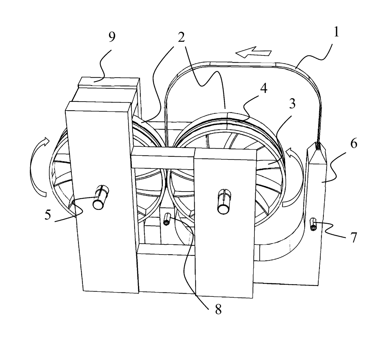
[0035]The present invention, in one aspect, discloses a compact thermoelastic cooling system that includes a set of rollers, a refri...


PUM


Abstract

A compact cooling system based on thermoelastic effect is provided. In one embodiment, the system comprises a pair of rollers serving as a heat sink, stress applicator and belt drive, a cold reservoir and a solid refrigerant belt coupled to the cold reservoir and to the heat sinks to pump heat from the cold reservoir to the heat sink. The refrigerant belt comprises solid thermoelastic materials capable of thermoelastic effect. The refrigerant material is mechanically compressed when entering the gap of the roller and subsequently released after passing through. When compressed the refrigerant material transforms to martensite phase and releases heat to the roller and neighboring materials. After released by the rollers, the refrigerant material transforms back to austenite and absorbs heat from the ambient atmosphere.

Description

GOVERNMENT SUPPORT[0001]This invention was made with government support under DE-EE0007043 awarded by Department of Energy. The government has certain rights in the invention.BACKGROUND[0002]The invention relates to systems and materials used for solid-state thermodynamic heat pump cycles or refrigeration cycles. More particularly, the invention relates to solid-state thermodynamic heat pump cycles or refrigeration cycles based on thermoelastic effect.[0003]Thermoelastic cooling technology based on thermoelastic effect is known in the art. It is often referred to as elastocaloric effect when the underlying science is discussed, and referred to as thermoelastic effect when the engineering and application aspects are discussed. Similar to the vapor compression cooling technology, the thermoelastic method relies on latent heat released or absorbed during the stress induced solid-to-solid phase transition. Tests of the thermoelastic refrigerant have demonstrated cooling efficiency as hi...

Claims


Application Information

Patent Timeline
IPC IPC(8): F25B23/00C09K5/14
CPCC09K5/14F25B23/00C09K5/10F28D17/00F28D19/00
Inventor CUI, JUNTAKEUCHI, ICHIRO
Owner CUI JUN
Why Eureka
Try Eureka