Color filter substrate and liquid crystal display panel

a color filter substrate and liquid crystal display technology, applied in the field of display technology, can solve the problems of reducing the brightness of the display substrate, and reducing the brightness of the display, so as to achieve high brightness and high color saturation.

Active Publication Date: 2017-05-18
TCL CHINA STAR OPTOELECTRONICS TECH CO LTD
View PDF6 Cites 5 Cited by
  • Summary
  • Abstract
  • Description
  • Claims
  • Application Information

AI Technical Summary

Benefits of technology

[0007]An objective of the present invention is to provide a color filter substrate, capable of controlling the color change of the filters and possessing high brightness and high color saturation.

Problems solved by technology

One important reason is that the present color filter substrate cannot satisfy the demands of the high brightness and the high color saturation at the same time.
Although there already has a method of adding white (W) matrix to obtain the RGBW display matrix for acquiring the high brightness liquid crystal display device, the color saturation will be weakened as increasing the brightness.
The demands of the high brightness and the high color saturation cannot be satisfied at the same time.
Therefore, the electrochromic material possesses a certain potential to be applied in the display device field and draws tons of attention.

Method used


Image

  • Color filter substrate and liquid crystal display panel
  • Color filter substrate and liquid crystal display panel
  • Color filter substrate and liquid crystal display panel

Examples


Embodiment Construction

[0045]For better explaining the technical solution and the effect of the present invention, the present invention will be further described in detail with the accompanying drawings and the specific embodiments.

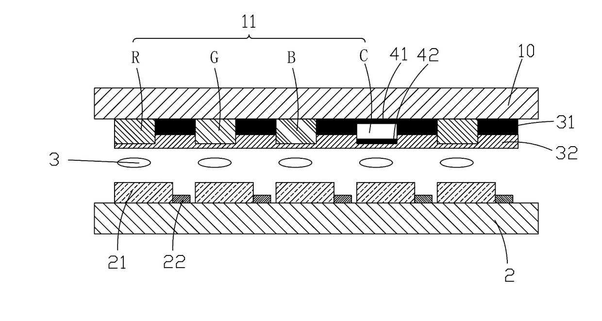
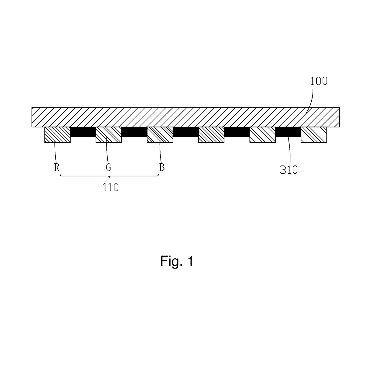
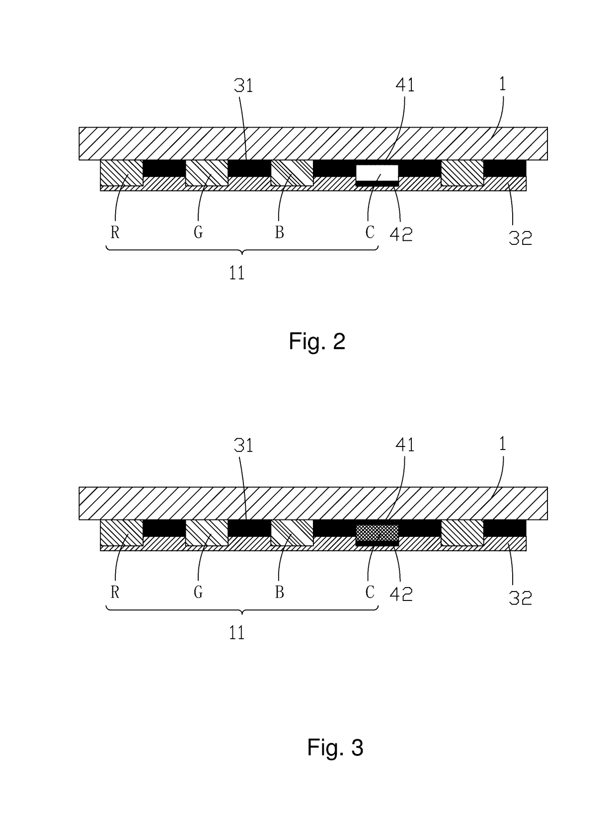
[0046]Please refer to FIG. 2, FIG. 3. The present invention first provides a color filter substrate, comprising a substrate 1, a color filter layer 11 positioned on the substrate 1 and a protective layer 32 positioned on the color filter layer 11.

[0047]The color filter layer 11 comprises a plurality of red filters R, green filters G, blue filters B and color change filters C aligned in matrix, and a first transparent electrode 41 and a second transparent electrode 42 are respectively positioned at two sides of the color change filter C; a black matrix 31 separates the plurality of red filters R, the green filters G, the blue filters B and the color change filters C aligned in matrix.

[0048]Material of the color change filter C is electrochromic material, and the color change fi...


PUM

PropertyMeasurementUnit
transparentaaaaaaaaaa
electrochromicaaaaaaaaaa
coloraaaaaaaaaa

Abstract

The present invention provides a color filter substrate and a liquid crystal display panel. Both comprises a color filter layer (11) having a plurality of red filters, green filters, blue filters (R, G, B) and color change filters (C) aligned in matrix, and a first transparent electrode (41) and a second transparent electrode (42) are respectively positioned at two sides of the color change filter (C), and material of the color change filter (C) is electrochromic material. The color change filter (C) is applied with voltage signals via the first transparent electrode (41) and the second transparent electrode (42) to control color change of the color change filter (C) for conveniently achieving high brightness and high color saturation display; as appearing to be transparent, the transmission is high to satisfy the demand of high brightness display; as the color change filter (C) appears to be a specific color which is not red, green, blue, such as cyan, four colors display can be realized to promote the color expression ability to satisfy the demand of high color saturation display.

Description

FIELD OF THE INVENTION[0001]The present invention relates to a display technology field, and more particularly to a color filter substrate and a liquid crystal display panel.BACKGROUND OF THE INVENTION[0002]The LCD (Liquid Crystal Display) possesses advantages of thin body, power saving and no radiation to be widely used in many application scope. It has been widely utilized in, such as mobile phones, PDAs (personal digital assistance), digital cameras, laptop screens or notebook screens.[0003]The present thin film transistor liquid crystal display comprises a shell, a LCD panel located in the shell and a backlight module located in the shell. The structure of the liquid crystal display panel mainly comprises a Thin Film Transistor Array Substrate (TFT Array Substrate), a Color Filter (CF) and a Liquid Crystal Layer arranged between the two substrates. Generally, the thin film transistor array substrate comprises scan lines, data lines, thin film transistors and pixel electrodes; th...

Claims


Application Information

Patent Timeline
Patent Type & Authority Applications(United States)
IPC IPC(8): G02F1/1335G02F1/1368G02B5/20G02B5/22G02F1/155G02F1/157
CPCG02F1/133514G02F1/155G02F1/157G02B5/201G02F2001/136222G02F1/133512G02F1/1368G02F2201/44G02B5/223G02F1/1343G02F1/1347G02F1/15G02F1/136222
Inventor YU, XIAOPING
Owner TCL CHINA STAR OPTOELECTRONICS TECH CO LTD
Why Eureka
Try Eureka