Systems and Methods for Detection of Plasma Instability by Optical Diagnosis

Active Publication Date: 2017-05-18
LAM RES CORP
View PDF7 Cites 6 Cited by
  • Summary
  • Abstract
  • Description
  • Claims
  • Application Information

AI Technical Summary

Benefits of technology

[0005]In an example embodiment, a method is disclosed for plasma processing of a wafer. The method includes positioning a wafer on a wafer support apparatus. The wafer support apparatus is positioned beneath an electrode such that a plasma generation region exists between the wafer and the electrode. The method also includes supplying radiofrequency power to the electrode to generate a plasma within the plasma generation region. The method also includes collecting optical emissions from

Problems solved by technology

However, in some plasma processes, the above-mentioned process parameters may not provide for adequate control of all plasm

Method used


Image

  • Systems and Methods for Detection of Plasma Instability by Optical Diagnosis
  • Systems and Methods for Detection of Plasma Instability by Optical Diagnosis
  • Systems and Methods for Detection of Plasma Instability by Optical Diagnosis

Examples


Embodiment Construction

[0028]In the following description, numerous specific details are set forth in order to provide a thorough understanding of the present invention. It will be apparent, however, to one skilled in the art that the present invention may be practiced without some or all of these specific details. In other instances, well known process operations have not been described in detail in order not to unnecessarily obscure the present invention.

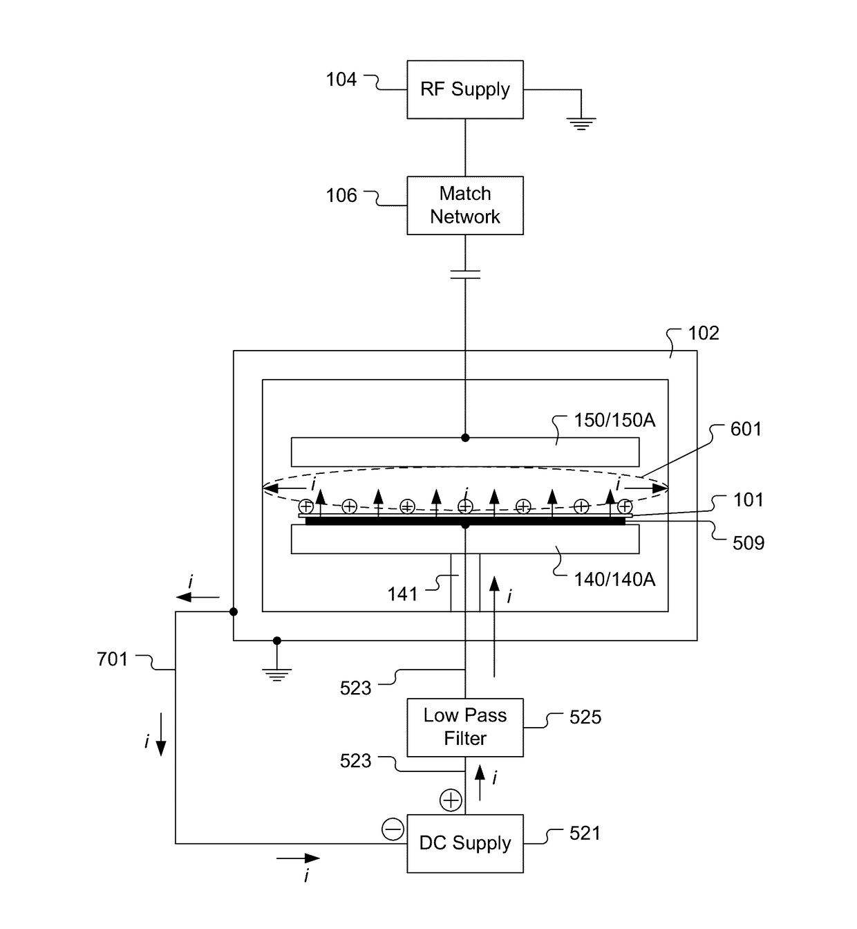
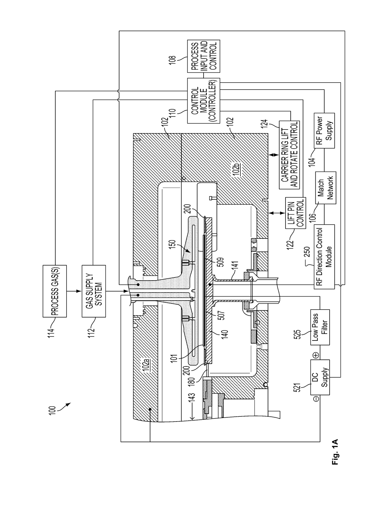
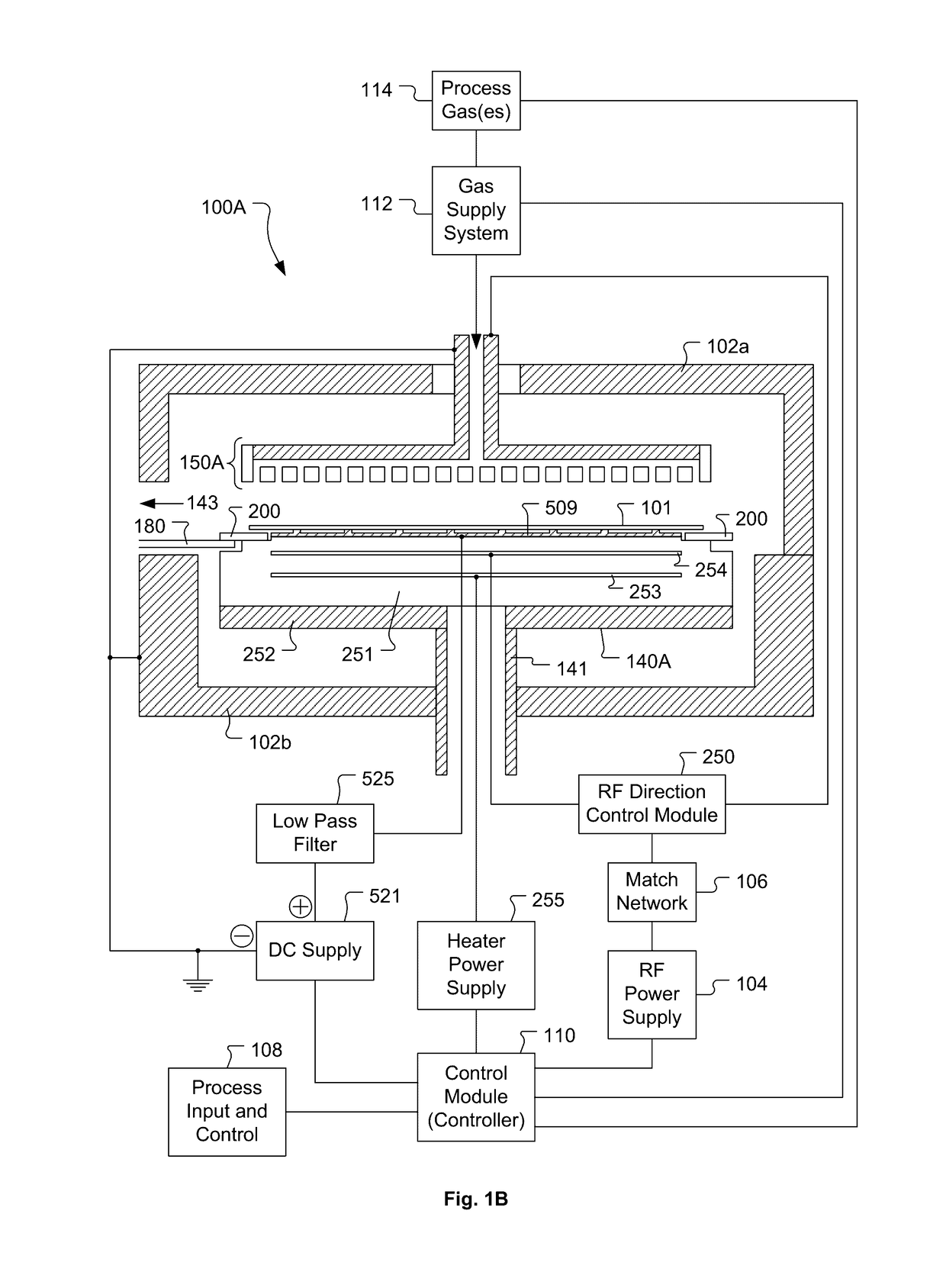
[0029]Deposition of films can be implemented in a plasma enhanced chemical vapor deposition (PECVD) system. The PECVD system may take many different forms. The PECVD system includes one or more chambers or “reactors” (sometimes including multiple stations) that house one or more wafers and are suitable for wafer processing. Each chamber may house one or more wafers for processing. The one or more chambers maintain the wafer in a defined position or positions (with or without motion within that position, e.g. rotation, vibration, or other agitation). A w...


PUM

PropertyMeasurementUnit
Pressureaaaaaaaaaa
Pressureaaaaaaaaaa
Distanceaaaaaaaaaa

Abstract

A wafer is positioned on a wafer support apparatus beneath an electrode such that a plasma generation region exists between the wafer and the electrode. Radiofrequency power is supplied to the electrode to generate a plasma within the plasma generation region. Optical emissions are collected from the plasma using one or more optical emission collection devices, such as optical fibers, charge coupled device cameras, photodiodes, or the like. The collected optical emissions are analyzed to determine whether or not an optical signature of a plasma instability exists in the collected optical emissions. Upon determining that the optical signature of the plasma instability does exist in the collected optical emissions, at least one plasma generation parameter is adjusted to mitigate formation of the plasma instability.

Description

CLAIM OF PRIORITY[0001]This application claims priority under 35 U.S.C. 119(e) to U.S. Provisional Patent Application No. 62 / 256,682, filed Nov. 17, 2015, the disclosure of which is incorporated herein by reference in its entirety for all purposes.BACKGROUND1. Field of the Invention[0002]The present invention relates to semiconductor device fabrication.2. Description of the Related Art[0003]Many modern semiconductor chip fabrication processes include generation of a plasma from which ions and / or radical constituents are derived for use in either directly or indirectly affecting a change on a surface of a wafer exposed to the plasma. For example, various plasma-based processes can be used to etch material from a wafer surface, deposit material onto a wafer surface, or modify a material already present on a wafer surface. The plasma is often generated by applying radiofrequency (RF) power to a process gas in a controlled environment, such that the process gas becomes energized and tra...

Claims


Application Information

Patent Timeline
IPC IPC(8): H01L21/66H01J37/32C23C16/52H01L21/263C23C16/50
CPCH01L22/20H01L22/12H01L21/263H01J37/3299C23C16/52H01J37/32137C23C16/50H01J37/32082H01J37/32155H01J37/32935H01J37/32917H01L21/268C23C16/45565C23C16/4585C23C16/4586C23C16/509H01J37/32091H01L21/67201H01L21/02315H01L21/3065H01L21/02274H05H1/46H01L21/0234H01L21/6719H01J37/32715H01J2237/334H01L21/67069H01L21/683H01L21/02164H01L21/0228
Inventor SAKIYAMA, YUKINORIAUGUSTYNIAK, EDWARDKEIL, DOUGLAS
Owner LAM RES CORP
Why Eureka
Try Eureka