System-Level Camera Module with Electrical Support and Manufacturing Method Thereof

a camera module and system-level technology, applied in the field of camera modules, can solve the problems of reducing affecting the quality of the product, and affecting the service life of the entire camera module, so as to reduce the inclination of the module, improve the product quality, and high-efficiency mass production

Active Publication Date: 2017-05-18
NINGBO SUNNY OPOTECH CO LTD
View PDF9 Cites 9 Cited by
  • Summary
  • Abstract
  • Description
  • Claims
  • Application Information

AI Technical Summary

Benefits of technology

[0025]Another object of the present invention is to provide a camera module with electrical support and the manufacturing method thereof, wherein the production of the camera module can use imposition manner which is suitable for high efficient massive production.
[0026]Another object of the present invention is to provide a camera module with electrical support and the manufacturing method thereof, wherein the electrical support substitutes the base in conventional camera module which can reduce the inclination of module caused by the base so as to improve the product quality.
[0027]Another object of the present invention is to provide a camera module with electrical support and the manufacturing method thereof, wherein the camera module has a small size and a securely connecting structure.
[0028]Another object of the present invention is to provide a camera module with electrical support and the manufacturing method thereof, wherein the camera module has a small overall dimension, wherein the height of the camera module can be reduced 0.25 mm comparing with the conventional COB packaging method and the overall dimensions can be reduced more than 0.5 mm.
[0029]Another object of the present invention is to provide a camera module with electrical support and the manufacturing method thereof, wherein the camera module manufacturing process is simplified, wherein the driver is directly attached to the circuit board, which reduces the soldering process, shorten the production cycle and reduces production costs.
[0030]Another object of the present invention is to provide a camera module with electrical support and the manufacturing method thereof, wherein the electrical support has strong market competitiveness, thus enhance the market competitiveness of the camera module using the electrical support, and further enhance the market competitiveness of the electronic equipment using the camera module in high-end products market.

Problems solved by technology

For example, the camera module as a standard component in a portable electronic device has tendency toward lightness and thinness to be installed in the portable electronic device.
Firstly, the driver 2 has a protruded conductor which is electrically connected to the circuit board 7, so that the motor 2 is electrically connected to the circuit board 7. The conductor is connected to the circuit board 7 through the solder joint 9. The process to connect the motor 2 and the circuit board 7 through a protruded conductor is complicated, and will generate many other problems, such as the product quality might be influenced by the soldering quality. Moreover, this soldering connection by soldering the protruded conductor is not solid, which would be easily damaged during operation or maintenance process.
Such electrical connection is not secured.
Furthermore, the conductor, the metal wire 5 and the drive control module 6 are vulnerable to external environment, such as the dust, etc., so as to affect the quality of the entire camera module and to reduce the service life of the entire camera module.
As mentioned above, the connection between the circuit board 7 and the photosensitive chip 8 together with the connection between the motor 2 and the circuit board 7 that both takes certain large space and are difficult to get good protection.
In addition, the base holder 4 is hardly able to provide enough protection to other electronic components in the camera module.
It cannot provide a full protection from dust or other contaminants.

Method used


Image

  • System-Level Camera Module with Electrical Support and Manufacturing Method Thereof
  • System-Level Camera Module with Electrical Support and Manufacturing Method Thereof
  • System-Level Camera Module with Electrical Support and Manufacturing Method Thereof

Examples


Embodiment Construction

[0108]The following description is disclosed to enable any person skilled in the art to make and use the present invention. Preferred embodiments are provided in the following description only as examples and modifications will be apparent to those skilled in the art. The general principles defined in the following description would be applied to other embodiments, alternatives, modifications, equivalents, and applications without departing from the spirit and scope of the present invention.

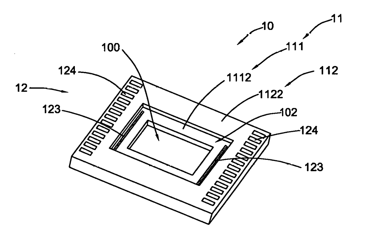
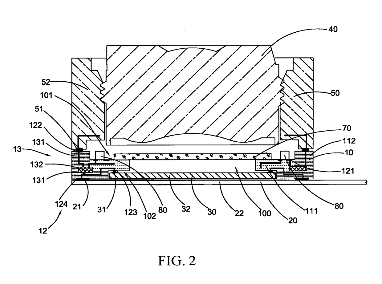
[0109]Referring to FIGS. 2 and 3, a system level camera module according to a preferred embodiment of the present invention is illustrated. The camera module comprises am electrical support 10, a flexible PCB 20, a photosensitive sensor 30 such as a photosensitive chip, an optical lens 40 and a driver 50 such as a motor. It is worth mention that the driver 50 serves as a focusing mechanism, such that the system level camera module of the present invention can be an auto-focus camera module. The c...


PUM


Abstract

A camera module includes an optical lens, a photosensitive chip and an electrical support. The electrical support includes a circuit module embedded in a support body to form an integral structure, a connecting member provided on the support body to electrically connect with the circuit module, and a camera component coupled at the support body and electrically connected to the connecting member. Therefore, the electrical support not only forms a circuit board to electrically connect with the camera component but only serves as a base to support the camera component.

Description

CROSS REFERENCE OF RELATED APPLICATION[0001]This is a Continuation application that claims the benefit of priority under 35 U.S.C. §119 to a non-provisional application, application Ser. No. 15 / 057,057, filed Feb. 29, 2016, and the benefit of priority under 35 U.S.C. §120 to Chinese application number CN 201510778437.2, filing date Nov. 13, 2015, and Chinese application number CN 201610099510.8, filing data Feb. 23, 2016, the entire contents of each of which are expressly incorporated herein by reference.NOTICE OF COPYRIGHT[0002]A portion of the disclosure of this patent document contains material which is subject to copyright protection. The copyright owner has no objection to any reproduction by anyone of the patent disclosure, as it appears in the United States Patent and Trademark Office patent files or records, but otherwise reserves all copyright rights whatsoever.BACKGROUND OF THE PRESENT INVENTION[0003]Field of Invention[0004]The present invention relates to a camera module,...

Claims


Application Information

Patent Timeline
Patent Type & Authority Applications(United States)
IPC IPC(8): H04N5/225
CPCH04N5/2252H04N5/2253H04N23/50H04N23/55H04N23/54H01L27/14618H04N23/51G02B5/208G02B7/006H05K3/32H04N23/57
Inventor WANG, MINGZHUZHAO, BOJIECHEN, FEIFANDING, LIANGGUO, NANWU, YEJIANG, HENG
Owner NINGBO SUNNY OPOTECH CO LTD
Why Eureka
Try Eureka