Battery pack for energy storage devices

a technology for energy storage devices and battery packs, applied in the direction of cell components, electrical equipment, electrochemical generators, etc., can solve the problems of cell cooling, performance, longevity, safety, and severe problems, and achieve the effect of improving efficiency and reducing costs

Active Publication Date: 2017-05-25
INSTREETCARICRON
View PDF5 Cites 26 Cited by
  • Summary
  • Abstract
  • Description
  • Claims
  • Application Information

AI Technical Summary

Benefits of technology

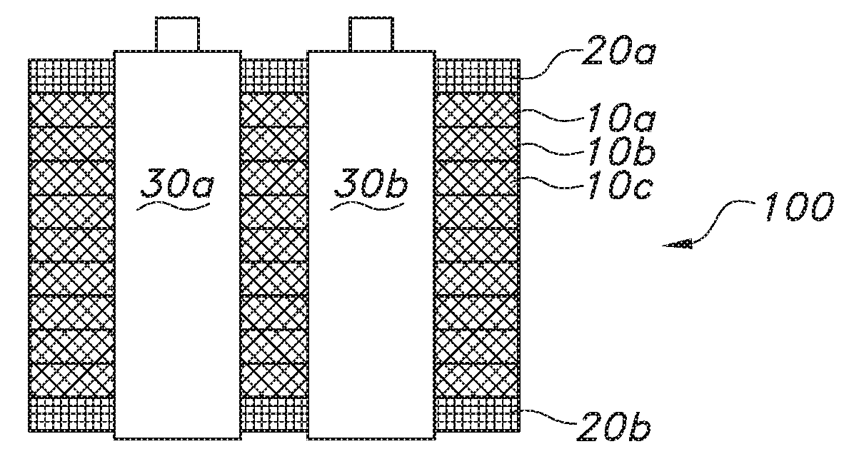
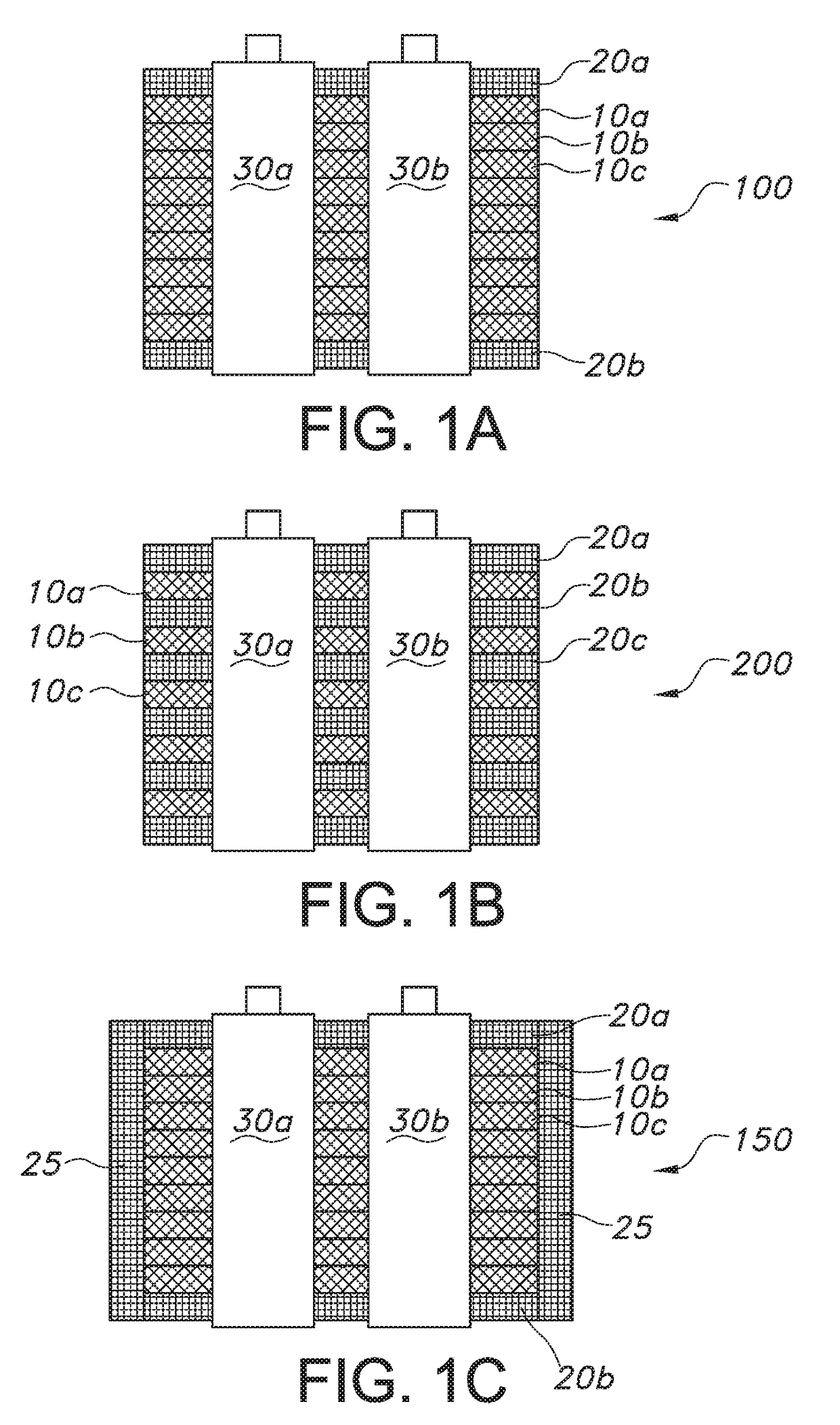
[0006]Battery packs for high energy density batteries (cells), particularly arrays of such batteries are described herein. The battery packs include a microfibrous media (MFM)-phase change materials (PCM) composite block, and one or more active cooling structures. End plates are also included on the upper and lower surfaces of t...

Problems solved by technology

Heat generation within Li-ion cells causes problems for performance, longevity, and safety, especially for those power cells required to be continuously discharged at extremely high currents.
However, the issue can be severe when...

Method used


Image

  • Battery pack for energy storage devices
  • Battery pack for energy storage devices
  • Battery pack for energy storage devices

Examples


example

[0095]The battery cooling performance of a battery pack with MFM-PCM and cooling tubes, where the MFM was sintered to the cooling tubes, was calculated using experimental performance and COMSOL simulation results for a number of different battery packs. A representative example is described below.

[0096]The overall heat transfer rate was calculated using the experimental performance and COMSOL simulation results. For a MFM-PCM battery pack with cooling tubes sintered to the MFM and twelve midform (i.e., 223 mm long and diameter of 54 mm) cells in series (12 S), the overall heat transfer rate was determined to be 600 W / m2 K. The MFM-PCM block was pressed and sintered and contained 30% metal fiber (copper fibers, 12 micron diameter) and 70% PCM (paraffin wax).

[0097]The overall heat transfer rate was determined using an overall energy balance. The 12 S pack was placed in a 58° C. oven and continuously charged and discharged at C-rates of 4 C (120 Amp) and 15 C (450 Amp), respectively. T...


PUM


Abstract

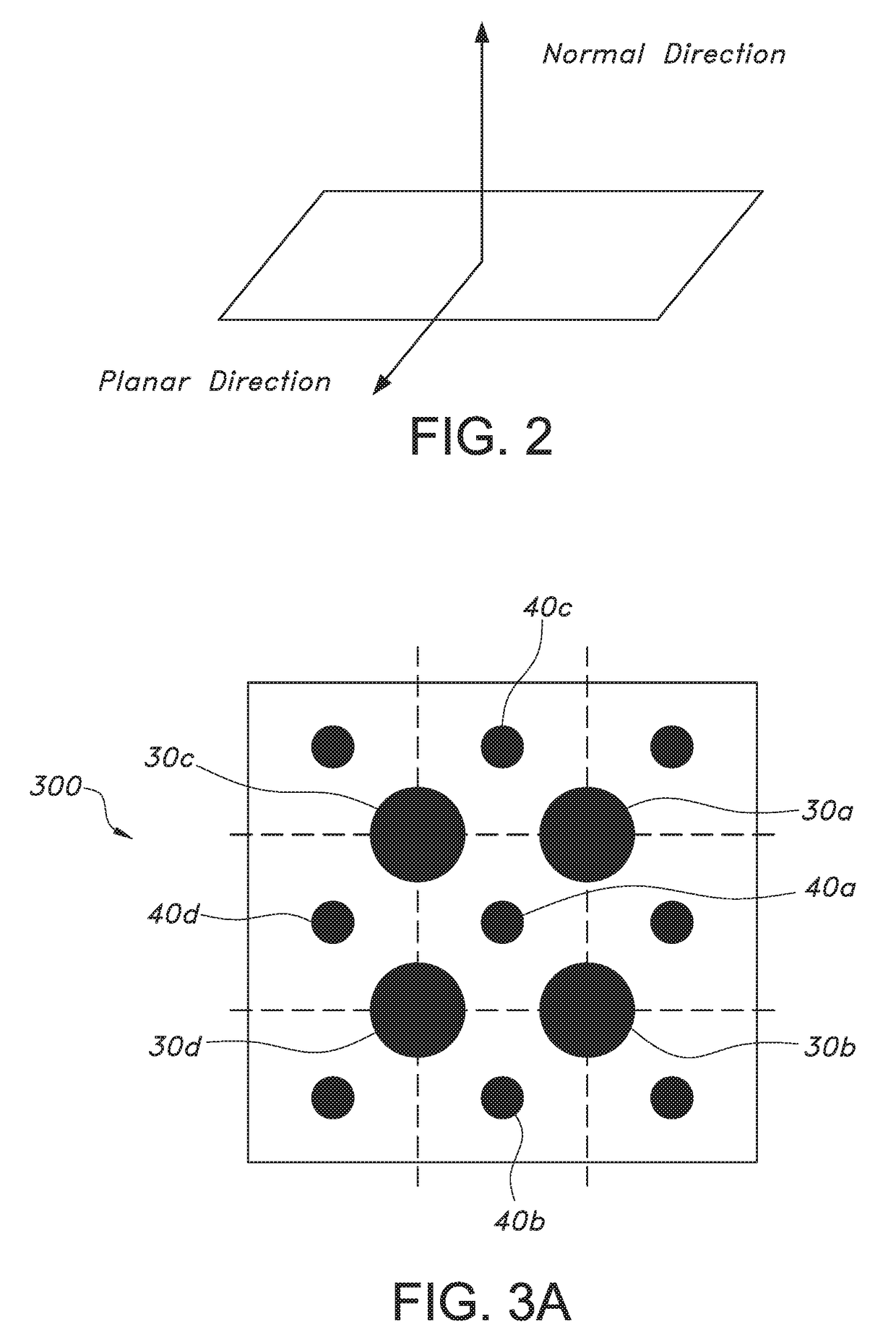
Battery packs for high energy density batteries (cells), particularly arrays of such batteries are described herein. The battery packs include a microfibrous media (MFM)-phase change materials (PCM) composite block and one or more active cooling structures. The MFM is typically sintered to the active cooling structures. The battery packs may contain more than one MFM-PCM composite block. Additionally or alternatively, the MFM-PCM composite block may contain different layers containing different MFM-PCM composites, which have different functionalities. In a preferred embodiment, at least one layer contains a flame retardant PCM, while at least one other layer contains a PCM with a lower melting temperature. The cells may be arranged in a repeating square or equilateral triangle pattern, with one or more active cooling structures in the geometric center of the square or triangle.

Description

CROSS-REFERENCE TO RELATED APPLICATION[0001]This application claims priority to U.S. Provisional Application No. 62 / 257,305,filed Nov. 19, 2015, the disclosure of which is incorporated herein by reference in its entirety.FIELD OF THE INVENTION[0002]The invention is generally directed to thermal management systems for energy storage cells having high charge / discharge currents, such as batteries and other electronic devices.BACKGROUND OF THE INVENTION[0003]Lithium ion (Li-ion) cells have been widely used for power and energy applications. Heat generation within Li-ion cells causes problems for performance, longevity, and safety, especially for those power cells required to be continuously discharged at extremely high currents. It may not be a significant issue for individual cells operated in ambient air even when they are discharged at their highest allowable currents. However, the issue can be severe when the cells are discharged in an assembled battery pack. In a battery pack, a ce...

Claims


Application Information

Patent Timeline
IPC IPC(8): H01M10/653H01M2/10H01M10/643H01M10/6556H01M10/6568H01M10/658H01M10/0525H01M10/613
CPCH01M10/653H01M10/0525H01M2/1016H01M10/643H01M10/6556H01M10/6568H01M10/658H01M10/613Y02E60/10
Inventor YANG, HONGYUNBARRON, TROYTATARCHUK, BRUCEDIMICK, PAUL
Owner INSTREETCARICRON
Why Eureka
Try Eureka