Charging circuit and mobile terminal

Active Publication Date: 2017-05-25
GUANGDONG OPPO MOBILE TELECOMM CORP LTD
View PDF8 Cites 4 Cited by
  • Summary
  • Abstract
  • Description
  • Claims
  • Application Information

AI Technical Summary

Benefits of technology

The patent proposes a charging circuit and a mobile terminal to improve its reliability. The circuit blocks direct current (DC) power signals, preventing them from causing damage or malfunction. This results in a more stable charging process.

Problems solved by technology

In conventional technology, there is a risk of the breakdown of the MOS transistor, which can result in that an overcurrent flows through the inductor, and the battery.
Furthermore, the battery may be improperly charged to exceed the threshold voltage thereof, thereby causing a failure of the battery.
1. Improper operation of the MOS transistor caused by voltage applied across two terminals of the MOS transistor in excess of the threshold voltage, electrostatic breakdown, or surge current impact;
2. Poor quality of the MOS transistor or defects in manufacturing;
However, high on-resistance RDS(ON) may cause heat accumulation of the MOS transistor due to current heating effect and a low power transmission efficiency of the charging circuit.

Method used


Image

  • Charging circuit and mobile terminal
  • Charging circuit and mobile terminal
  • Charging circuit and mobile terminal

Examples


Embodiment Construction

[0030]Embodiments of the present disclosure are described in detail with the technical matters, structural features, achieved objects, and effects with reference to the accompanying drawings as follows. Specifically, the terminologies in the embodiments of the present disclosure are merely for describing the purpose of the certain embodiment, but not to limit the invention.

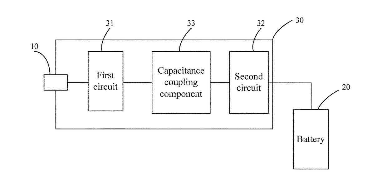
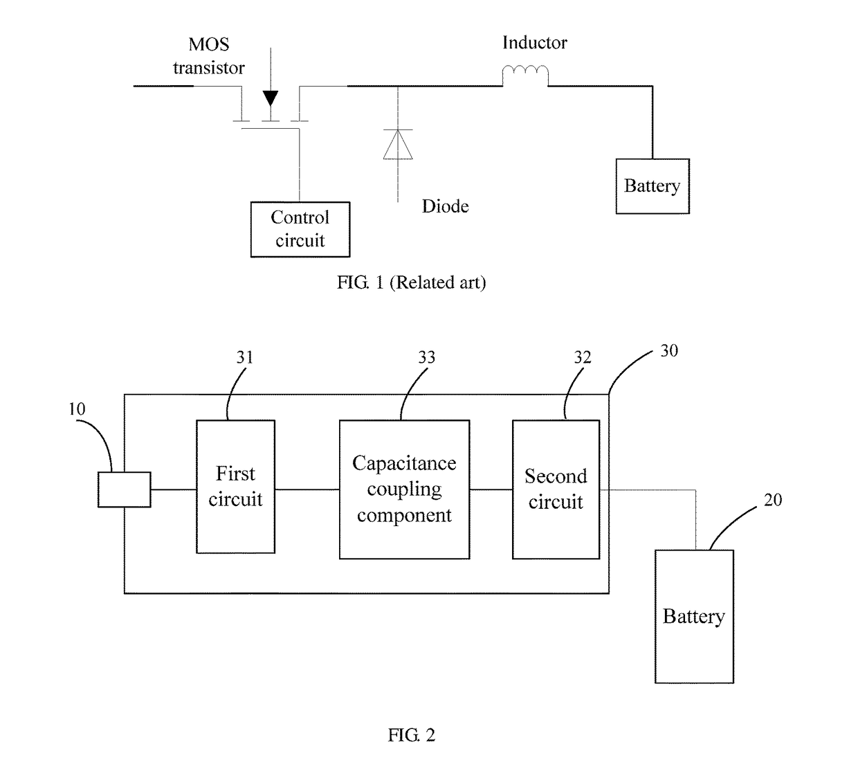
[0031]FIG. 2 is a block diagram of a charging circuit 30 according to an embodiment of the present disclosure. The charging circuit 30 illustrated in FIG. 2 is coupled between a charging port 10 of a mobile terminal and a battery 20. The charging circuit 30 includes the following components.

[0032]A first circuit 31 is coupled to the charging port 10. The first circuit 31 is configured to draw direct current (DC) power signal via the charging port 10 from an electrical power source and convert direct current (DC) power signal flowing through the charging port 10 to alternating current (AC) power signal.

[0033]A seco...


PUM


Abstract

The present disclosure proposes a charging circuit and a mobile terminal. The charging circuit includes: a first circuit, coupled to a charging port, to draw DC power signal, and convert the DC power signal into AC power signal; a second circuit, coupled to the battery, configured to receive the AC power signal from the first circuit, and convert the AC power signal into DC power signal for charging the battery; a capacitance coupling component, coupled between the first circuit and the second circuit. The capacitance coupling component is configured to block DC power signal from the first circuit. That is, the DC power signal fails to pass through the first circuit. Thus, the DC power signal flowing through the charging port does not flow to the second circuit and the battery directly when the first circuit malfunctions. Accordingly, the stability of the charging circuit is enhanced.

Description

BACKGROUND OF THE DISCLOSURE[0001]1. Field of the Disclosure[0002]The present disclosure relates to field of mobile terminals, and more particularly, to a charging circuit and a mobile terminal.[0003]2. Description of the Related Art[0004]Since mobile terminals are widely popular, the suppliers pay more attention on battery charging of the mobile terminals.[0005]FIG. 1 is a circuit diagram of a charging circuit used in a mobile terminal. The charging circuit, called a BUCK circuit, includes a metal oxide semiconductor (MOS) transistor, a control circuit, a diode, an inductor, and a battery. When the mobile terminal is charged, the control circuit controls the MOS transistor to alternatively turn on / off, so as to produce alternating current (AC) square wave signal. The square wave alternating current from the MOS transistor is first regulated by the inductor and then flows through the battery.[0006]In conventional technology, there is a risk of the breakdown of the MOS transistor, wh...

Claims


Application Information

Patent Timeline
IPC IPC(8): H02J7/00
CPCH02J7/0068H02J7/345H02J7/0045H02J2007/10H02J7/0029H02J7/06H02M7/04H02M7/5387H02J7/00H02M3/33523H02J7/02H02J2207/20H02J7/0031H04M1/0277
Inventor ZHANG, JIALIANG
Owner GUANGDONG OPPO MOBILE TELECOMM CORP LTD
Why Eureka
Try Eureka