Switching Circuit And Power Conversion Circuit

Active Publication Date: 2017-05-25
TOYOTA JIDOSHA KK
View PDF1 Cites 12 Cited by
  • Summary
  • Abstract
  • Description
  • Claims
  • Application Information

AI Technical Summary

Benefits of technology

[0006]In the switching circuit including a charge pump unit, it is possible to generate a negative voltage in the charge pump unit using a pulse signal for turning on/off a vo

Problems solved by technology

However, if such a configuration is used, the switching speed of the voltage-driven switching element decreases, and a switching loss increases.
For this reason, the turn-off speed of the voltage-driven switching element SM decreases, and an increase in switching l

Method used


Image

  • Switching Circuit And Power Conversion Circuit
  • Switching Circuit And Power Conversion Circuit
  • Switching Circuit And Power Conversion Circuit

Examples


Embodiment Construction

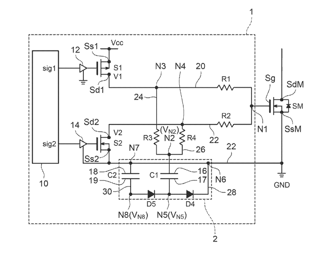
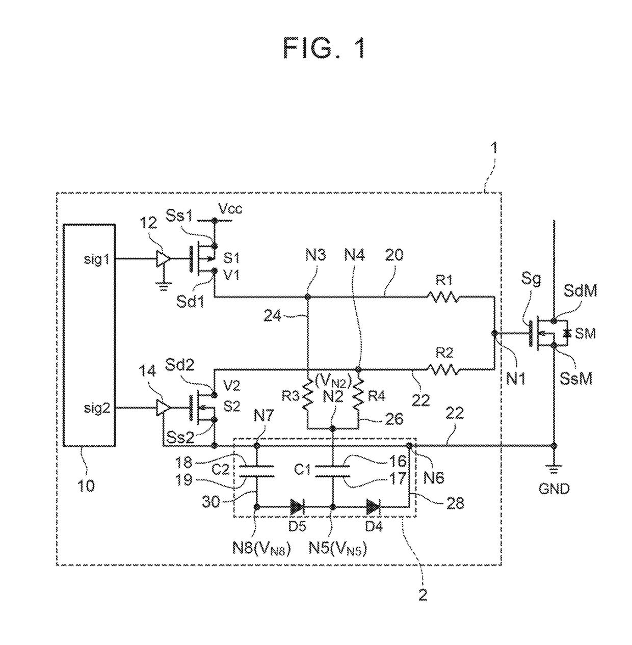
[0028]FIG. 1 is a circuit diagram of a switching circuit 1 which drives a voltage-driven switching element SM (hereinafter, simply referred to as a switching element SM). The switching circuit 1 of this example switches the on and off states of the switching element SM. The switching element SM is a power semiconductor element having an insulating gate, and specifically, is an n-channel type MOSFET. The switching element SM is configured such that a drain SdM and a source SsM are brought into an electric conduction state in a state where a gate turn-on voltage is applied to a gate Sg, and the drain SdM and the source SsM are brought into a non-electric conduction state in a state (gate turn-off state) where the gate turn-on voltage is not applied to the gate Sg. The switching element SM includes a reflux diode. The switching element SM is provided in a power conversion circuit, such as an inverter device which converts a DC voltage to an AC voltage.

[0029]The switching circuit 1 incl...


PUM


Abstract

A first switching element and a gate of a voltage-driven switching element are connected by a gate turn-on wiring through a first resistor. The gate of the voltage-driven switching element and a second switching element are connected by a gate turn-off wiring through a second resistor. A charge pump unit has a first capacitor, and a second capacitor configured to output a negative voltage. A resistor unit is arranged in at least one of a first wiring configured to connect the gate turn-on wiring and the first capacitor and a second wiring configured to connect the gate turn-off wiring and the first capacitor, and is configured to charge the first capacitor through the first wiring when the first switching element is turned on and to discharge the first capacitor through the second wiring when the second switching element is turned on.

Description

INCORPORATION BY REFERENCE[0001]The disclosure of Japanese Patent Application No. 2015-229094 filed on Nov. 24, 2015 including the specification, drawings and abstract is incorporated herein by reference in its entirety.BACKGROUND[0002]1. Field of the Disclosure[0003]A technique disclosed in this specification relates to a switching circuit and a power conversion circuit. In detail, a technique disclosed in this specification relates to a switching circuit including a charge pump unit and a power conversion circuit.[0004]2. Description of Related Art[0005]A voltage-driven switching element, such as an IGBT or a MOSFET, is used for various purposes, and for example, is used for a power conversion circuit, such as a converter device which transforms a DC voltage or an inverter device which converts a DC voltage to an AC voltage. In order to drive the voltage-driven switching element, a switching element which operates based on a control signal is used. The switching circuit is configu...

Claims


Application Information

Patent Timeline
IPC IPC(8): H02M3/07
CPCH02M3/07H03K17/04123H02M1/08H02M1/084H02M1/088H02M1/096H03K2017/066H03K2217/0036H03K2217/0081
Inventor OSANAI, YOSUKE
Owner TOYOTA JIDOSHA KK
Why Eureka
Try Eureka