Microphone and Method of Operating a Microphone

a microphone and microphone technology, applied in the field of microphones, can solve the problems of diaphragm collapse and change of capacitance of transducers, and achieve the effect of improving the method and improving the properties

Active Publication Date: 2017-05-25
TDK CORPARATION
View PDF6 Cites 15 Cited by
  • Summary
  • Abstract
  • Description
  • Claims
  • Application Information

AI Technical Summary

Benefits of technology

[0005]Embodiments of the invention provide a microphone with impr

Problems solved by technology

In particular, an acoustical input signal may result in a change of capacitance of the transducer.
When th

Method used


Image

  • Microphone and Method of Operating a Microphone
  • Microphone and Method of Operating a Microphone
  • Microphone and Method of Operating a Microphone

Examples


first embodiment

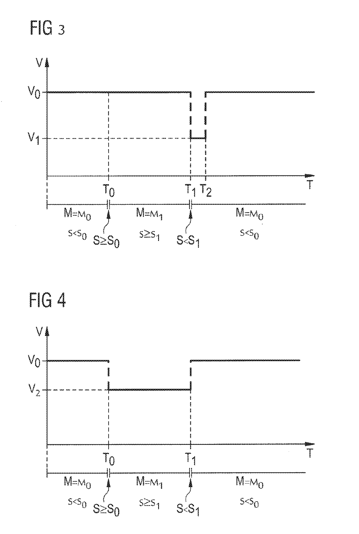
[0053]FIG. 3 shows a schematic diagram of a bias voltage V as a function of time T during a collapse event according to a

[0054]Initially, the microphone is in the normal operating mode MO, in which the voltage supply supplies an operating voltage VO. The signal level S is below the threshold value SO. At a time TO the mode controller detects that the signal level S has reached or exceeded the threshold value SO and, accordingly, switches to the collapse mode M1.

[0055]In this embodiment, the bias voltage is maintained at the value VO in the collapse mode. Due to the high bias voltage, the diaphragm may remain in the collapsed state. In this state, the diaphragm deflection is limited to the non-collapsed parts of the diaphragm. This will lower the electrical signal of the transducer as compared to a non-collapsed state, for example by 10 dB to 20 dB, depending on the diaphragm design.

[0056]The mode controller continuously checks the signal level. As long as the signal reaches or excee...

second embodiment

[0061]FIG. 4 shows a schematic diagram of a bias voltage as a function of time during a collapse event according to a

[0062]Initially, the microphone is in the normal operating mode MO, in which the voltage supply supplies an operating voltage VO. At a time TO the mode controller detects that the signal level S has reached or exceeded the threshold value SO and the mode is switched to the collapse mode M1.

[0063]In this embodiment, when the mode is switched to the collapse mode, the bias voltage is lowered to a level V2. The value of V2 is below a diaphragm release voltage such that the diaphragm is enabled to release from the back-plate. The value of V2 may be higher than the value of V1 of FIG. 3. Preferably, the value of V2 is significantly smaller than the value of the operating voltage VO. As an example, the value of V2 may be in a range of 1 V to 4 V. The value of VO may be in a range of 8 V to 15 V. As an example, due to the lower bias voltage, the output signal may be reduced ...


PUM


Abstract

A microphone and a method for operating a Microphone are disclosed. In an embodiment the microphone includes a transducer and a mode controller. The microphone has a normal operating mode (MO) and a collapse mode (M1). The mode controller switches to the collapse mode (M1) when an output signal of the transducer reaches or exceeds a predefined threshold value and switches to the normal operating mode (MO) when the output signal reaches or falls below a predefined further threshold value (S1).

Description

[0001]This patent application is a national phase filing under section 371 of PCT / EP2014 / 060335, filed May 20, 2014, which is incorporated herein by reference in its entirety.TECHNICAL FIELD[0002]The present disclosure relates to a microphone, in particular a condenser MEMS (Micro-Electrical-Mechanical Systems) microphone, and a method of operating a microphone. The microphone may comprise a single-ended or differential transducer. When the microphone is subjected to very high sound pressure levels, a collapse of the transducer may occur.BACKGROUND[0003]U.S. Pat. No. 5,870,482 discloses a miniature silicon condenser microphone wherein a movement of a diaphragm is limited for preventing a collapse. Patent application[0004]EP 1 599 067 A2 is directed to a method for detecting and controlling a diaphragm collapse in condenser microphones.SUMMARY OF THE INVENTION[0005]Embodiments of the invention provide a microphone with improved properties and an improved method for operating a microp...

Claims


Application Information

Patent Timeline
IPC IPC(8): H04R3/00H03G3/30H04R3/04
CPCH04R3/002H04R19/04H03G3/301H04R3/04H04R3/007H04R2201/003
Inventor RAVNKILDE, JAN TUESIEGEL, CHRISTIANJUNGKUNZ, MATTHIASROCCA, GINONIELSEN, IVAN RIISLEIDL, ANTONROMBACH, PIRMIN HERMANN OTTO
Owner TDK CORPARATION
Why Eureka
Try Eureka