
Device for automatically mounting screw and automatically mounting system

a technology of automatic mounting and screw, applied in metal-working equipment, metal-working equipment, manufacturing tools, etc., can solve the problems of sharp rise in the labor cost of mounting screws by manual use, and reduce the efficiency of mounting, so as to improve production efficiency, reduce production costs, and improve product quality

Active Publication Date: 2017-06-08
SHENZHEN SKYWORTH RGB ELECTRONICS CO LTD
View PDF0 Cites 31 Cited by
  • Summary
  • Abstract
  • Description
  • Claims
  • Application Information

AI Technical Summary

Benefits of technology

The present invention is about a device that automatically assembles screws, which can replace the manual labor that currently exists. This device helps to reduce production costs, improve production efficiency, and increase product quality. It works by locating the ready-to-assemble product in a special position and driving a taking member to acquire the screw from a screw feeding member. The whole process is completely automatic, so no manual work is needed. This also avoids quality issues that may occur due to workers' physical or emotional qualities. Additionally, the device for automatically assembling screws does not experience fatigue, which can reduce production efficiency. Overall, this invention helps to improve the production process for products that require screw assembly.

Problems solved by technology

However, in recent years, the labor cost sharply rises, which causes that the labor cost of mounting screw by manual sharply rises, and the consistency of the product are low due to workers' physical qualities and emotions, furthermore when workers works for a long time, the mounting efficient reduces due to fatigue.

Method used


Image

  • Device for automatically mounting screw and automatically mounting system
  • Device for automatically mounting screw and automatically mounting system
  • Device for automatically mounting screw and automatically mounting system

Examples


Embodiment Construction

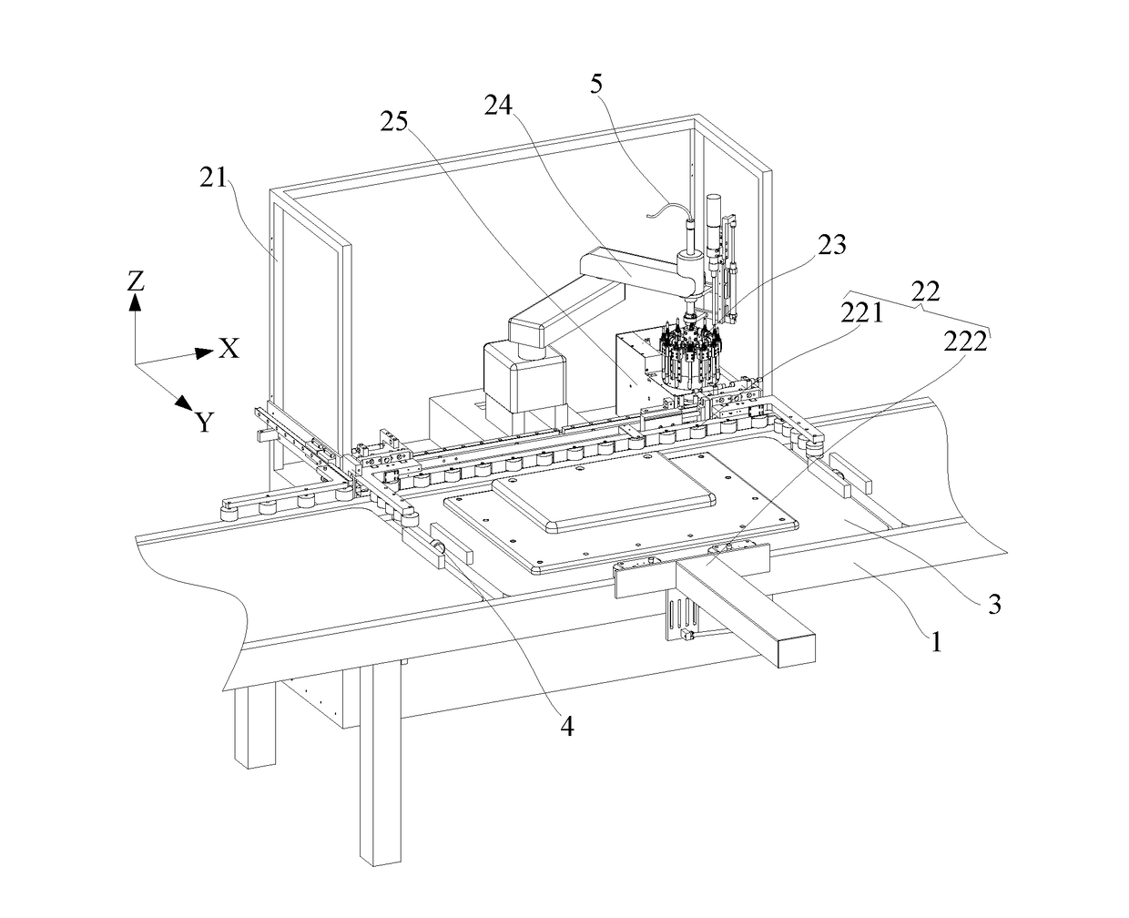
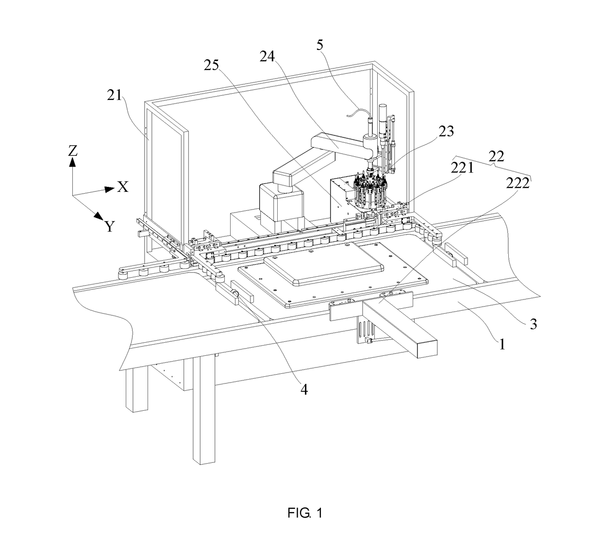
[0048]The technical solutions of the embodiments of the present disclosure will be clearly and completely described in the following with reference to the accompanying drawings. It is obvious that the embodiments to be described are only a part rather than all of the embodiments of the present invention. All other embodiments obtained by persons skilled in the art based on the embodiments of the present invention without creative efforts shall fall within the protection scope of the present invention.

[0049]It is to be understood that, the established XYZ rectangular coordinates according to FIG. 1 can be defined as that: a side of positive direction of X axis is right, a side of negative direction of X axis is left, and the right and the left can be defined as a horizontal direction; a side of positive direction of Y axis is back, a side of negative direction of Y axis is front, and the back and the front can be defined as a vertically direction; a side of positive direction of Z ax...


PUM

PropertyMeasurementUnit
Circumferenceaaaaaaaaaa

Abstract

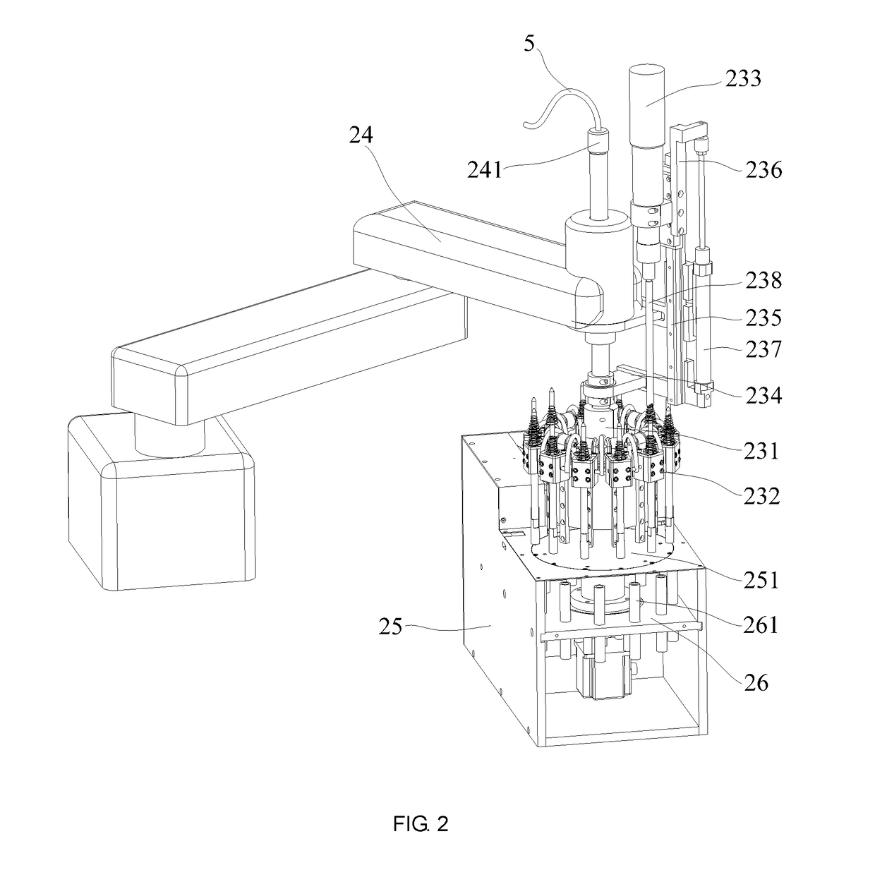
The invention discloses a device for automatically assembling screw and an automatically assembling system, the device includes a frame, a locating member, a taking member, a driving member and a screw feeding member: the locating member is for locating a product to special position; the taking member includes a rotating plate, at least three sucking elements fixed below the rotating member and located at a same circumference, and an electric screwdriver connected with the driving member and located upon the circumference; the driving member drives the rotating plate rotating, the electric screwdriver is movably located on the driving member; the screw feeding member includes a feeding plate including feeding positions, each feeding position corresponds to one sucking element; the (driving member drives the sucking element acquiring the screw, and drives the sucking element moving the acquired screw to a position for the electric screwdriver assembling the screw to the product.

Description

CROSS-REFERENCE TO RELATED APPLICATIONS[0001]This application is a continuation of International Patent Application No. PCT / CN2016 / 075869 with a filing date of Mar. 8, 2016, designating the United States, now pending, and further claims priority to Chinese Patent Application No. 201510875440.6 with a filing date of Dec. 2, 2015. The content of the aforementioned application, including any intervening amendments thereto, are incorporated herein by reference.TECHNICAL FIELD[0002]The present disclosure relates to the field of screw mounting technologies, and in particular, to a device for automatically mounting screw and an automatically mounting system.BACKGROUND OF THE PRESENT INVENTION[0003]The back cover of the electronic product such as the television, and other components are normally fixed with each other through screws. Currently, in the whole product production line of this kind of electronic product, components are normally fixed with each other through the screws by manual. ...

Claims


Application Information

Patent Timeline
IPC IPC(8): B23P19/04B23P19/10
CPCB23P19/105B23P19/04B23P19/001B23P19/06Y10T29/53374Y10T29/53383Y10T29/53313
Inventor YE, CHUANGWU, WEIYANG, JUNZHI
Owner SHENZHEN SKYWORTH RGB ELECTRONICS CO LTD
Learn More