Cooling Apparatus

US20170159142A1Inactive Publication Date: 2017-06-08METAL INDS RES & DEV CENT

Image

  • Cooling Apparatus
  • Cooling Apparatus
  • Cooling Apparatus

Examples


Embodiment Construction

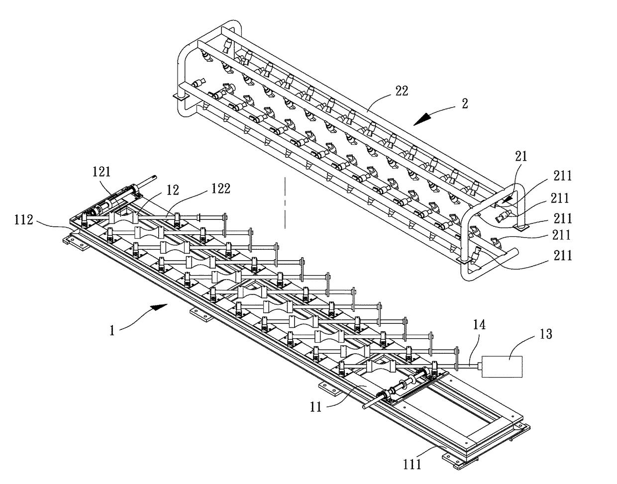
[0038]FIGS. 3 and 4 show a cooling apparatus according to an embodiment of the disclosure. The cooling apparatus includes a convoying unit 1 and a spraying unit 2. The spraying unit 2 is arranged at one side of the convoying unit 1.

[0039]Referring to FIGS. 3-5, the convoying unit 1 includes a base 11 and a plurality of rollers 12. The base 11 includes a feeding end 111 and a discharging end 112 in which a convoying direction D1 extends from the feeding end 111 to the discharging end 112. The rollers 12 are arranged on the base 11. Each of the rollers 12 includes a convoying portion 121. The convoying portion 121 has a diameter which reduces from two ends to the center thereof.

[0040]Referring to FIG. 6, the convoying portion 121 of the roller 12 has a varying diameter in this embodiment. The convoying portion 121 has an outer face which forms a curved face in a linear manner. In the embodiment, the outer face of the convoying portion 121 is in the form of a concave curved face. The c...


PUM

PropertyMeasurementUnit
Angleaaaaaaaaaa
Angleaaaaaaaaaa
Angleaaaaaaaaaa

Abstract

A cooling apparatus includes a convoying unit and a spraying unit. The convoying unit includes a base and a plurality of rollers. The base includes a feeding end and a discharging end in which a convoying direction extends from the feeding end to the discharging end. The rollers are arranged on the base. Each roller includes a convoying portion. The convoying portion has a diameter which reduces from two ends to a center thereof. Each roller includes a shaft. The shaft has an axle direction which is at a diverted angle to the convoying portion. The diverted angle is 15° to 90°. The spraying unit includes at least one nozzle unit arranged between the feeding end and the discharging end. In this arrangement, a cooling operation can be performed on a rod-shaped steel material that is moving and rotating at the same time, attaining uniform and fast cooling effect.

Description

CROSS REFERENCE TO RELATED APPLICATIONS[0001]The application claims the benefit of Taiwan application serial No. 104141192, filed on Dec. 8, 2015, and the subject matter of which is incorporated herein by reference.BACKGROUND OF THE INVENTION[0002]1. Field of the Invention[0003]The present disclosure generally relates to a cooling apparatus and, more particularly, to a cooling apparatus that can perform a cooling operation on a rod-shaped steel material.[0004]2. Description of the Related Art[0005]Heat treatment process is able to change the mechanical properties of a steel material during the processing of the steel material. The heat treatment process includes annealing, quenching and tempering. As an example of quenching, when a steel material is heated to a predetermined temperature, a cooling apparatus can perform a fast cooling operation on the steel material. In this regard, the cooling apparatus can change the metamorphosis of the steel material by controlling the cooling te...

Claims


Application Information

Patent Timeline
08 Jun 2017
Publication
US20170159142A1
IPC
C21D1/667; C21D9/52
CPC
C21D9/525; C21D1/667; B21B45/0224; B21B45/0233
Inventors
WANG, BO-HAN; WU, CHENG-EN