
Cyclic redundancy check generation via distributed time multiplexed linear feedback shift registers

a technology of cyclic redundancy check and shift register, applied in the field of data transfer, can solve problems such as cooler operation, and achieve the effects of less surface area of integrated circuit, cooler operation, and less power consumption

Active Publication Date: 2014-05-27
NVIDIA CORP
View PDF11 Cites 2 Cited by
  • Summary
  • Abstract
  • Description
  • Claims
  • Application Information

AI Technical Summary

Benefits of technology

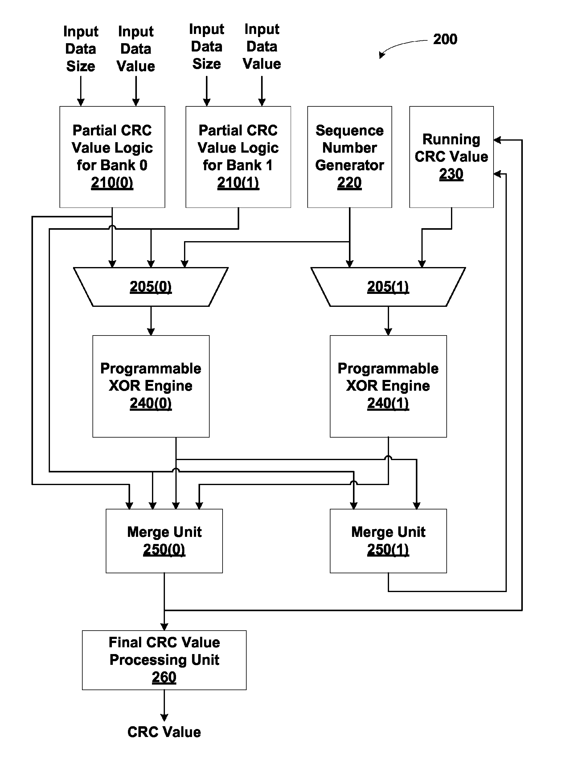
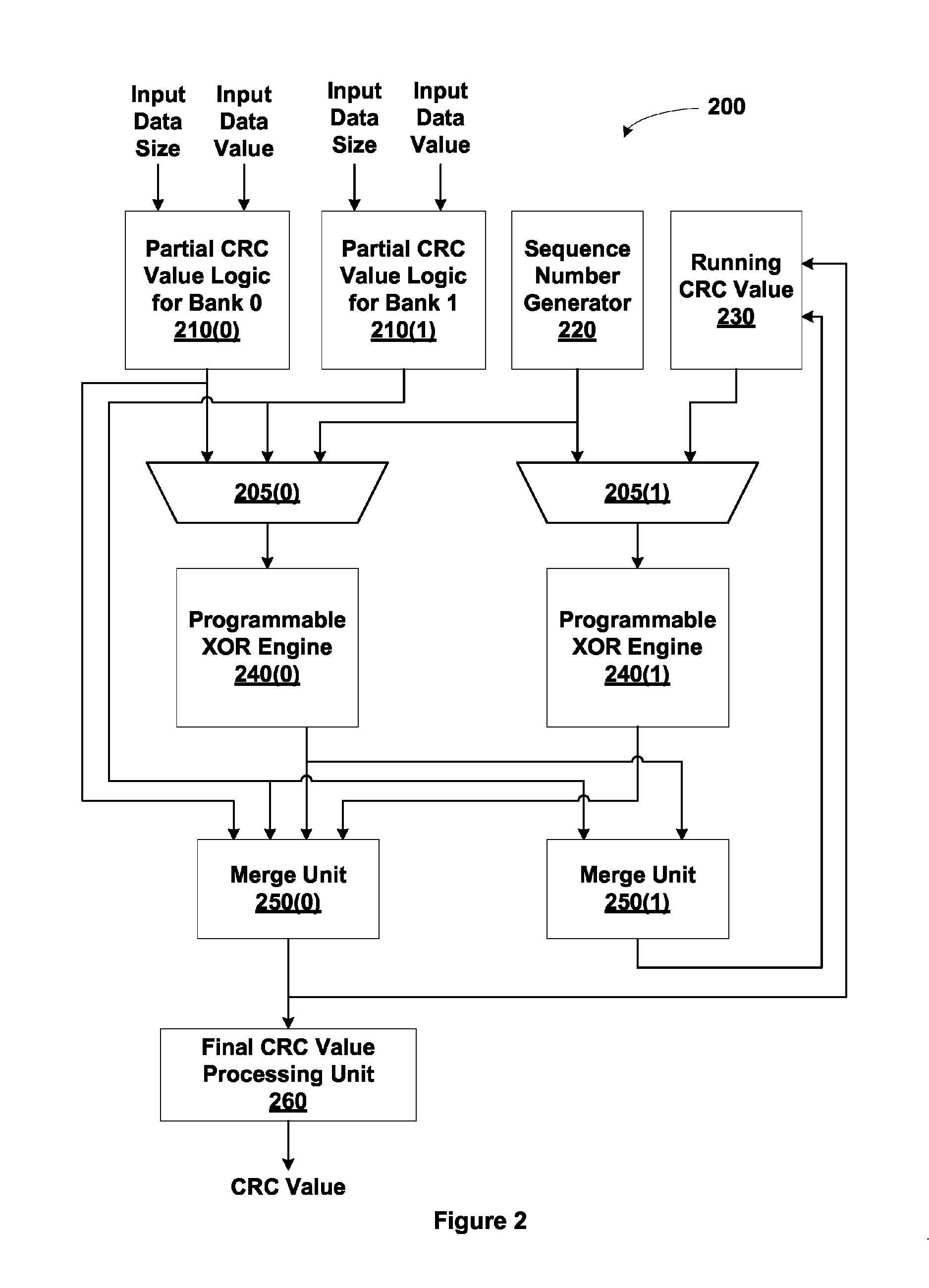
The present invention generates CRC values using smaller and fewer LFSR circuits than conventional circuit designs. This results in a CRC value generator that consumes less surface area and power, leading to cooler operation.

Problems solved by technology

As a result, a CRC value generator utilizing the disclosed techniques consumes less surface area of an integrated circuit and consumes less power, resulting in cooler operation.

Method used


Image

  • Cyclic redundancy check generation via distributed time multiplexed linear feedback shift registers
  • Cyclic redundancy check generation via distributed time multiplexed linear feedback shift registers
  • Cyclic redundancy check generation via distributed time multiplexed linear feedback shift registers

Examples


Embodiment Construction

[0021]In the following description, numerous specific details are set forth to provide a more thorough understanding of the present invention. However, it will be apparent to one of skill in the art that the present invention may be practiced without one or more of these specific details.

System Overview

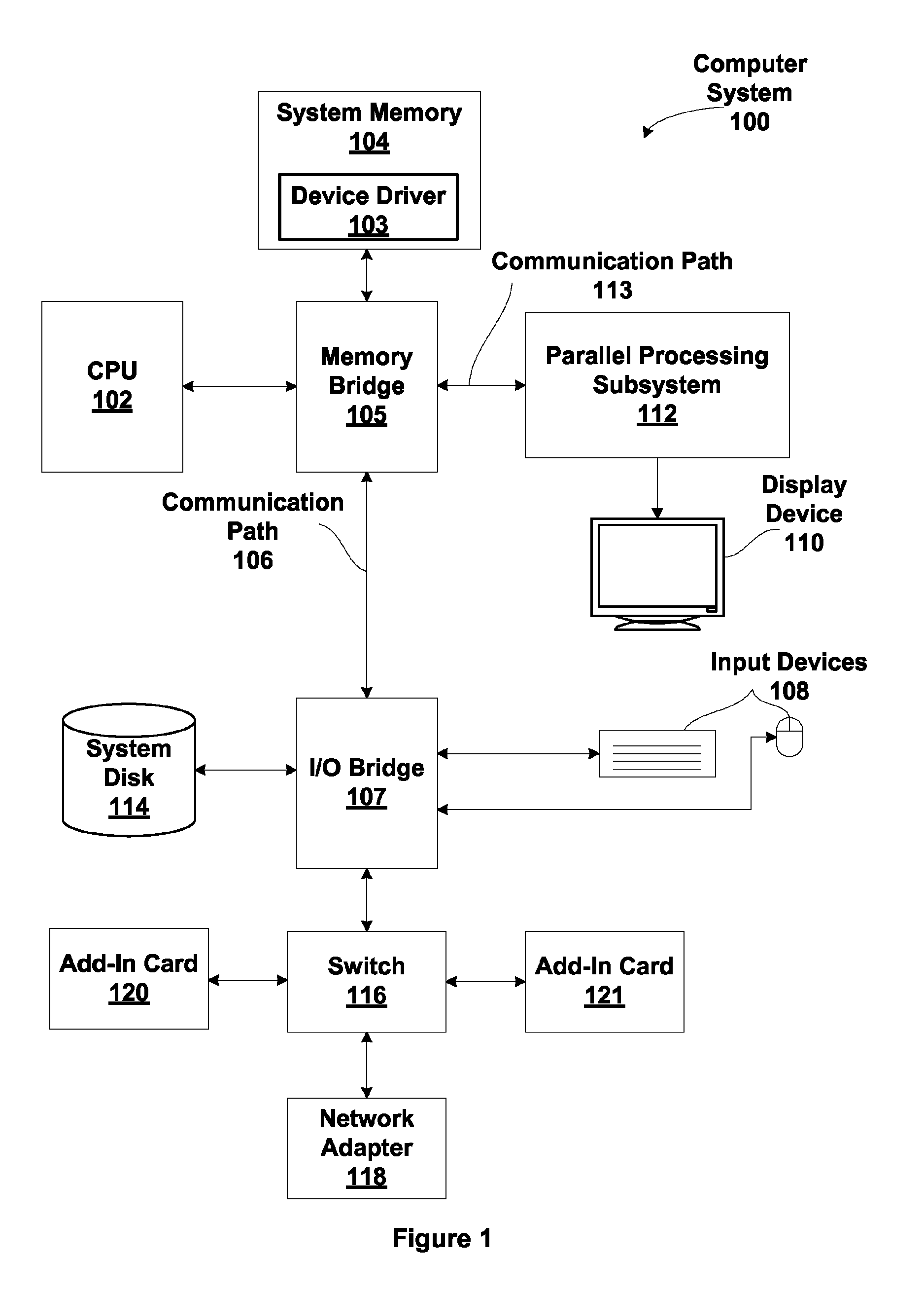
[0022]FIG. 1 is a block diagram illustrating a computer system 100 configured to implement one or more aspects of the present invention. Computer system 100 includes a central processing unit (CPU) 102 and a system memory 104 communicating via an interconnection path that may include a memory bridge 105. Memory bridge 105, which may be, e.g., a Northbridge chip, is connected via a bus or other communication path 106 (e.g., a HyperTransport link) to an I / O (input / output) bridge 107. I / O bridge 107, which may be, e.g., a Southbridge chip, receives user input from one or more user input devices 108 (e.g., keyboard, mouse) and forwards the input to CPU 102 via communication path 106 and m...


PUM


Abstract

Cyclic redundancy check (CRC) values are efficiently calculated using an improved linear feedback shift register (LFSR) circuit. CRC value generation is separated into two sub-calculations, which are then combined to form a final CRC value. A programmable XOR engine performs logic functions via a table lookup rather than via a random logic circuit. LCRC and ECRC calculations are performed using a single shared LFSR circuit. Multiple links share the same CRC value generator. One advantage of the present invention is that CRC values are generated using smaller and fewer LFSR circuits relative to conventional circuit designs. As a result, a CRC value generator utilizing the disclosed techniques consumes less surface area of an integrated circuit and consumes less power, resulting in cooler operation.

Description

BACKGROUND OF THE INVENTION[0001]1. Field of the Invention[0002]The present invention generally relates to data transfer within a computing environment and, more particularly, to cyclic redundancy check generation via distributed time multiplexed linear feedback shift registers.[0003]2. Description of the Related Art[0004]In modern computing environments, multiple devices are oftentimes interconnected to provide processing speed and flexibility within the computing environment. In such architectures, data exchanged between the interconnected devices is susceptible to corruption due to intermittent noise or other interruptions during transmission of the data from the source device to the receiving device. To detect such corruption, some computing environments employ a technique whereby a calculation is performed on the data to be transmitted, and the result of the calculation is transmitted by the source device along with the data. The receiving device performs the same calculation o...

Claims


Application Information

Patent Timeline
Patent Type & Authority Patents(United States)
IPC IPC(8): H03M13/00
CPCG06F11/10H04L1/0061H03M13/6575H03M13/09H03M13/6502H03M13/091
Inventor HILL, ERIC LYELLSCHOBER, JR., RICHARD L.CHA, HUNGSE
Owner NVIDIA CORP
Learn More