Device and System for Structural Health Monitoring

Inactive Publication Date: 2017-06-08
BROADSENS CORP JIAXING
View PDF6 Cites 14 Cited by
  • Summary
  • Abstract
  • Description
  • Claims
  • Application Information

AI Technical Summary

Benefits of technology

[0007]This invention integrates data acquisition and data processing into a single smart device, which greatly simplifies the electrical wiring need, reduces the overall footprints, and improves the reliability of a SHM system. The baseline information regarding the structure when it is in healthy condition is stored locally at the SHM device. A predefined threshold is also stored locally in the SHM device. The baseline information is used to determine if the structure defects exceed the safety operation boundary. The detection of structural changes and damages is performed directly by the smart SHM device. This allows instantaneous event detection in the shortest time frame, which is especially useful at time critical situations where the decision must be made as fast as possible. Because the detection of structural changes and damages is performed locally, a smart SHM device can continuously monitor a structure to detect damage, even when network connection is not available.
[0008]The smart SHM device does not need to send all sensor data to the remote management console across the network for processing. The sensor data, extracted features, and results of structural changes and damages are transmitted to the remote management console only when requested or scheduled. This dramatically reduce

Problems solved by technology

Such damages may include changes to the material and/or geometric properties of a structural system as well as changes to the boundary conditions and system connectivity, which adversely affect the structural system's performance.
However, these data acquisition devices do not have the capabilities to determine the structural changes and damages independently.
Any network glitches or failure will disrupt the monitoring of the structure.
This

Method used


Image

  • Device and System for Structural Health Monitoring
  • Device and System for Structural Health Monitoring
  • Device and System for Structural Health Monitoring

Examples


Embodiment Construction

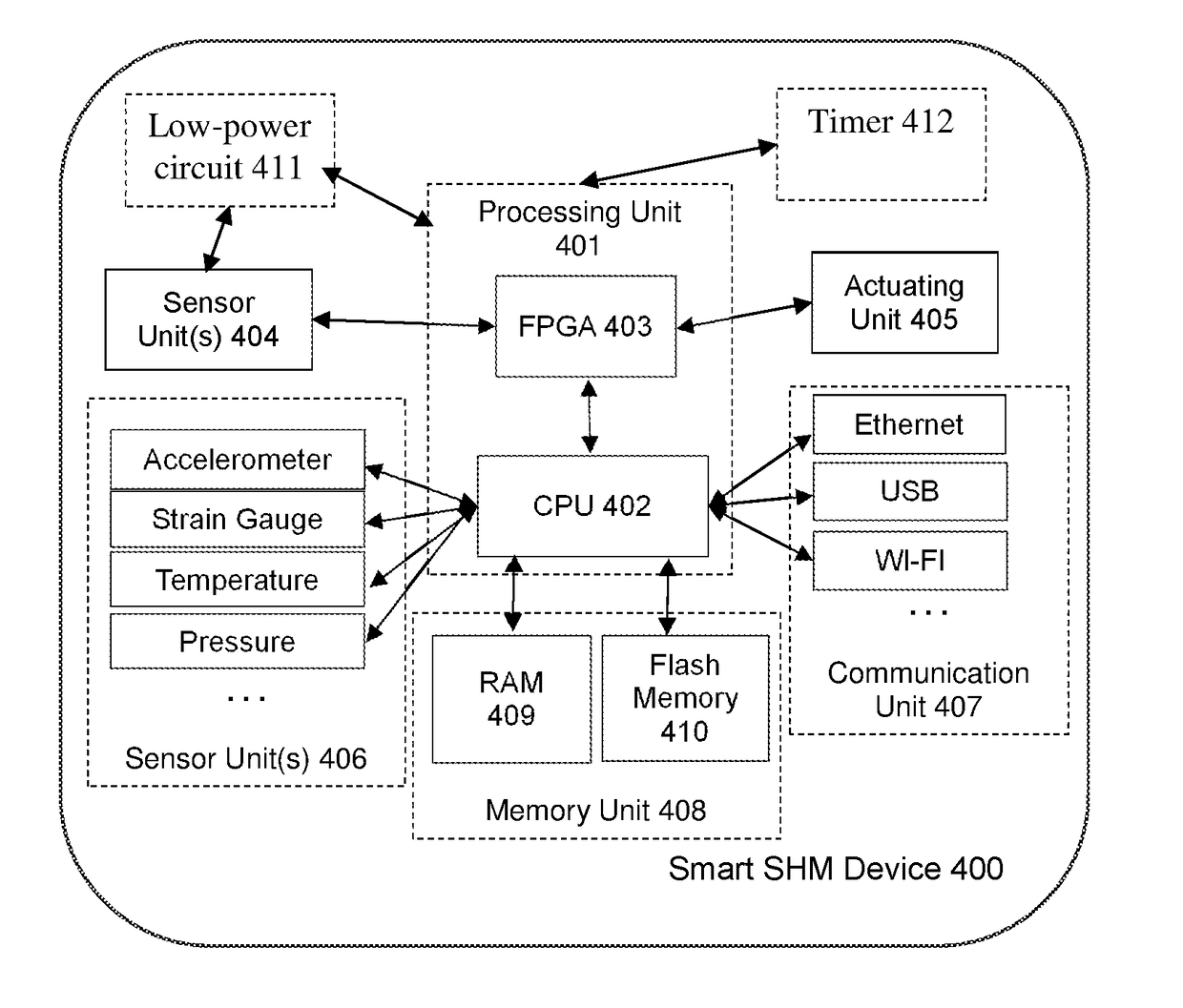
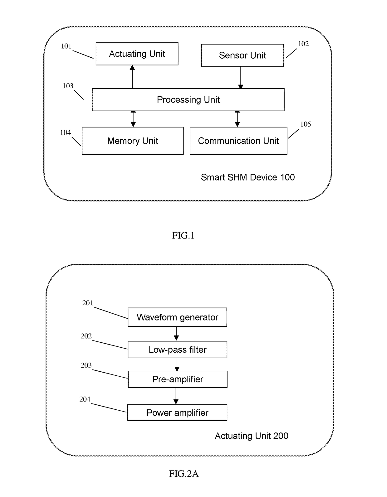
[0021]FIG. 1 illustrates a block diagram of a smart SHM device according to one embodiment of the invention. As shown, the smart SHM device 100 includes an actuating unit 101, a sensor unit 102, a processing unit 103, a memory unit 104, and a communication unit 105.

[0022]The actuating unit 101 and sensor unit 102 may include piezoelectric-based actuators and sensors or Electromagnetic Acoustic Transducer (EMAT)-based actuators and sensors, respective. In one embodiment of the invention, the actuating unit 101 and sensor unit 102 are installed inside the smart SHM device 100. During operation, the actuating unit 101 sends excitation signals across the structure and the sensor unit 102 receives the structure's response to the excitation signals. Alternatively, the actuating unit 101 and / or the sensor unit 102 may be connected externally to the smart SHM device 100 via connecters and / or cables. In this configuration, the actuating unit 101 and the sensor unit 102, or a number of these ...


PUM


Abstract

The present invention discloses a smart structural health monitoring device. The device is an intelligent sensor device mounted onto or near the structure to be monitored. The device includes an actuating unit that generates acoustic or ultrasonic excitation signals across the structure, a sensor unit that receives the structure's responses to the excitation signals and generates corresponding sensor data, a processing unit that determines the structure's structural health (e.g., structural change, structural defect, structural damage) by processing the sensor data with analytics algorithms. The smart device also includes at least a non-volatile memory (e.g., Flash memory) for storing the structural health information and sensor data. Such a smart structural health monitoring device is capable of independently determining the structural changes and damages. And multiple smart structural health monitoring devices can be used for monitoring one or more structures at the same time. A remote management console is used to configure, schedule, coordinate, and control the devices through a network. Each device transmits the results of structural changes and damages to the remote management console through according to a schedule or upon request.

Description

CROSS-REFERENCE TO RELATED APPLICATION[0001]This application claims priority to U.S. provisional patent application Ser. No. 62 / 261,866, filed Dec. 2, 2015, the entire content of which is incorporated herein by reference.FIELD OF INVENTION[0002]This invention generally relates to the field of structural health monitoring (“SHM”).BACKGROUND OF THE INVENTION[0003]SHM involves the process of implementing a damage detection and characterization strategy for engineering structures. Such damages may include changes to the material and / or geometric properties of a structural system as well as changes to the boundary conditions and system connectivity, which adversely affect the structural system's performance. The monitoring process may include the observation of a system over time using periodically sampled dynamic response measurements from an array of sensors, the extraction of damage-sensitive features from these measurements, and the statistical analysis of these features to determine...

Claims


Application Information

Patent Timeline
IPC IPC(8): G01N29/44G01N29/24G01N29/04
CPCG01N29/4427G01N29/04G01N2291/0289G01N29/2437G01N29/2412G01D21/02G01N29/043G01N2291/0258
Inventor ZHANG, CHANGLIU, LEI
Owner BROADSENS CORP JIAXING
Why Eureka
Try Eureka