
Water Control Gate Anchoring System and Method

a gate anchoring and water control technology, applied in the direction of hinges, door/window fittings, wing accessories, etc., can solve the problems of cracking and spalling, high cost of stainless steel anchor bolts and associated nuts and washers, and increase the height of damming, so as to eliminate undesirable bending moments, the effect of long service life and high gate system cos

Active Publication Date: 2017-06-15
OBERMEYER HENRY K
View PDF5 Cites 1 Cited by
  • Summary
  • Abstract
  • Description
  • Claims
  • Application Information

AI Technical Summary

Benefits of technology

The patent is about a cover for a clamp casting anchor bolt hole. The cover can be made of strong material and attached with screws, or it can be made of rubber and held in place by a lip at the top of the hole. The rubber cover can also have a smaller rubber plug inside it to help release air and fill the cavities in the hole with a substance that displaces water and oxygen. This leads to improved casting quality.

Problems solved by technology

The cost of using stainless steel for the anchor bolts and associated nuts and washers increases with damming height.
In the case of water control gates with higher damming heights (5 to 10 meters high, for example), it is more difficult and expensive to provide anchor bolts of sufficient diameter so it is desirable to provide a load path for the usually predominate upstream loads and for the occasional downstream loads separate from the anchor bolts.
Without a separate horizontal load path, this portion of concrete may be subjected to tensile loads that cause it to crack and spall off in response to impact loads in the downstream direction to the gate panels.
The cost of high strength stainless steel anchor bolts may be unacceptably high in the case of high gate systems.

Method used


Image

  • Water Control Gate Anchoring System and Method
  • Water Control Gate Anchoring System and Method
  • Water Control Gate Anchoring System and Method

Examples


Embodiment Construction

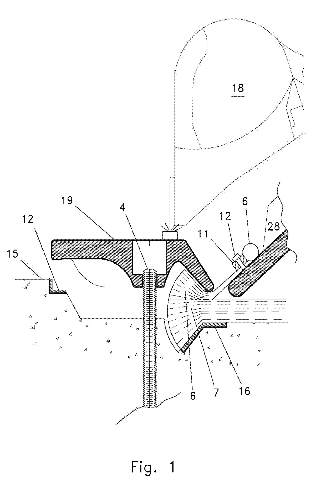
[0029]Referring to FIG. 1, prior art shows that compression of hinge flap 6 and air bladder 7 may require an externally applied downward force on clamp casting 19 such as from a hydraulic excavator bucket 18. It should be noted that the term “clamp casting” is used herein to describe the clamps which, although commonly cast, might also be made by forging, flame cutting, or additive manufacturing, for example.

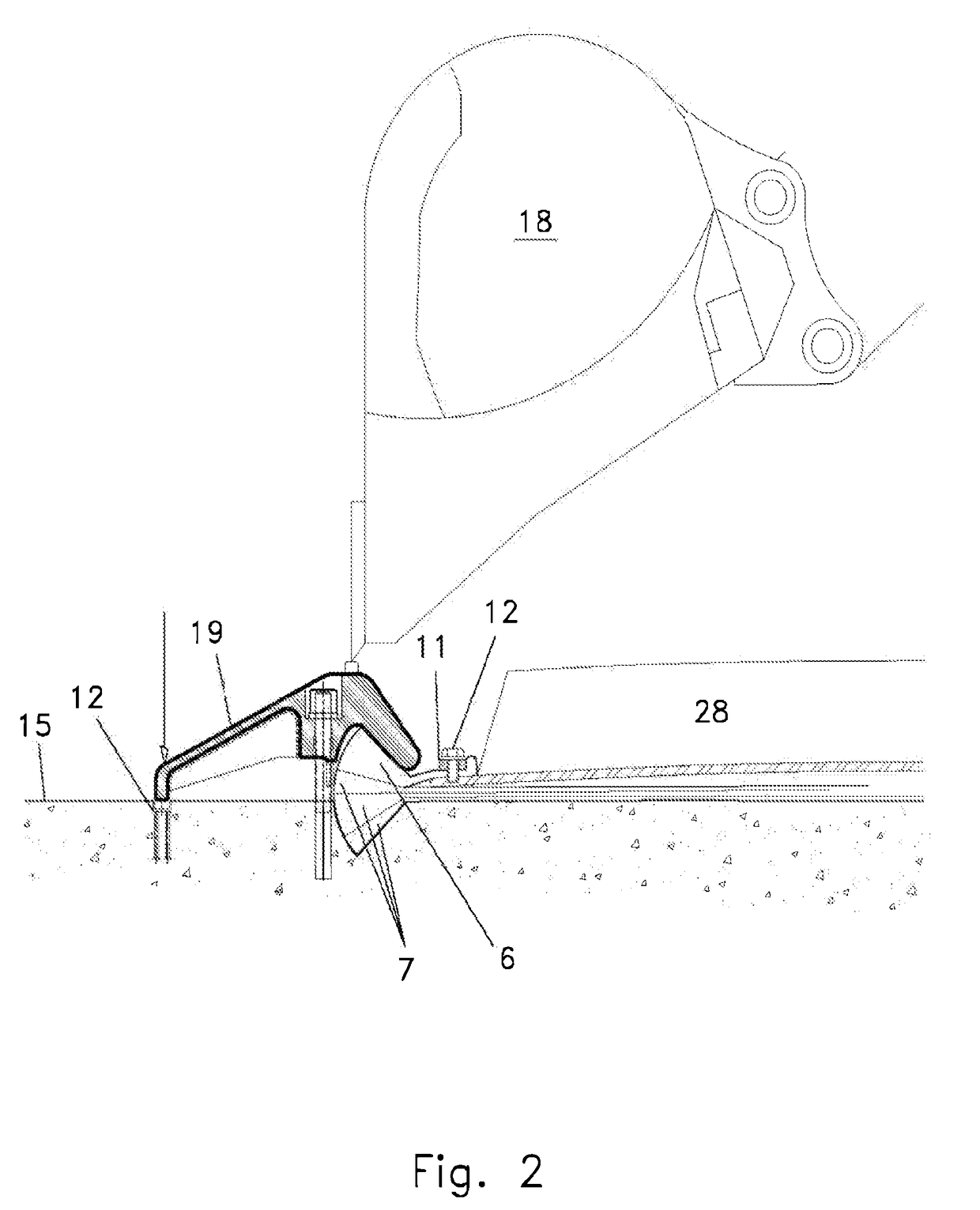
[0030]Referring to FIG. 2, prior art shows an external force such as from a hydraulic excavator bucket 18 may be required to seat non-pivoting clamp 19 against hinge flap 6 and air bladder 7.

[0031]Referring to FIG. 3, prior art clamp 19 is shown in its installed position against hinge flap 6 and air bladder 7. Upstream embed 12 in spillway (foundation) 15 provides horizontal restraint to clamp casting 19 once installation is complete. Gate panel 28 is shown attached to hinge flap 6 by means of hinge retainer 11 and bolt 12.

[0032]Referring to FIG. 4, prior art clamp 1 has moved d...


PUM


Abstract

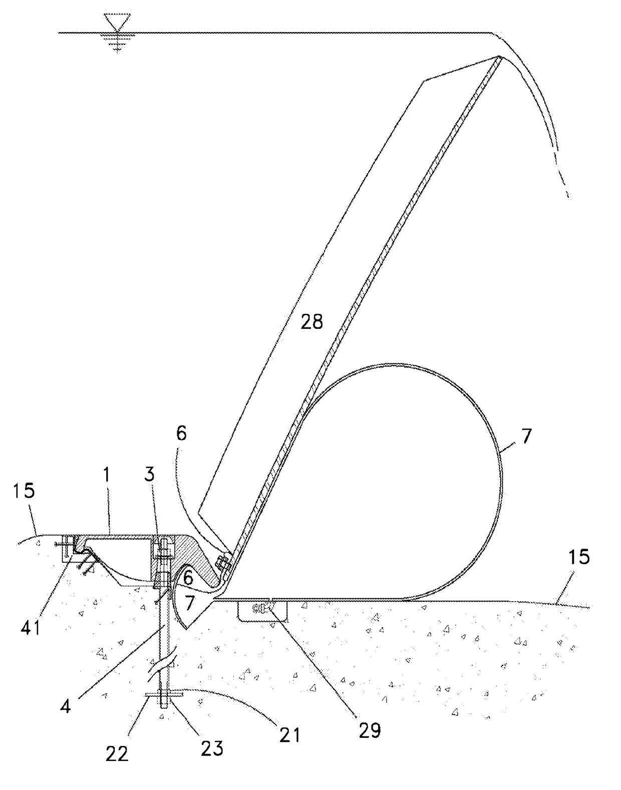
The present invention relates to inflatable bladder actuated water control gates for control of open channels such as rivers and canals and for control of dam spillways without the need for intermediate piers. The air bladder and hinge flap wedge clamping system includes hinged engagement of the upstream edge of the clamps to the foundation so as to prevent the application of bending and shear loads to the anchor bolts. The resulting configuration facilitates the use of high strength alloy steel anchor bolts in a corrosion protected environment and also prevents tensile loading of the concrete foundation and associated cracking of the concrete foundation.

Description

[0001]This application is the International Phase of and claims priority to U.S. Provisional Application No. 62 / 026,540 Jul. 18, 2014. Said application is incorporated herein by reference. It is noted that Jul. 18, 2015 was a Saturday, making this patent application due Jul. 20, 2015.FIELD OF INVENTION[0002]The present invention relates to the anchoring system for inflation operated bottom hinged water control gates. Such gates may be used, for example, for water storage, river diversion, hydropower impoundments, flood control, sea water barriers, spillway control, and the like.DESCRIPTION OF RELATED ART[0003]Prior art bottom hinged water control gates include gates operated by hydraulic cylinders from above, gates operated from hydraulic cylinders from below, gates operated by torque tubes extending into piers or abutments, overhead hoist operated gates, as well as pneumatically actuated bottom hinged gates.[0004]Inflation operated water control gates are well known. Prior art incl...

Claims


Application Information

Patent Timeline
Patent Type & Authority Applications(United States)
IPC IPC(8): E02B8/00E02B7/54E05D7/00E02B7/44E05D1/00
CPCE02B8/00E02B7/44E05Y2900/40E05D7/00E02B7/54E05D1/00E02B7/005
Inventor OBERMEYER, HENRY K.
Owner OBERMEYER HENRY K
Learn More