Exhaust gas dilution device and exhaust gas measuring system using the same

a technology of exhaust gas dilution and measuring system, which is applied in the direction of exhaust treatment electric control, machines/engines, instruments, etc., can solve the problems of changing engine combustion conditions, difficult to obtain a flow rate range exceeding the dilutable flow rate range, and inability to ensure the gas flow velocity at the orifice hol

Inactive Publication Date: 2017-06-15
HORIBA LTD
View PDF7 Cites 4 Cited by
  • Summary
  • Abstract
  • Description
  • Claims
  • Application Information

AI Technical Summary

Benefits of technology

[0022]The exhaust gas dilution device according to the present invention is capable of expanding a flow rate range, and therefore makes it possible to do various tests and also accept a test of internal combustion engines having variously-sized displacements.

Problems solved by technology

However, when increasing the gas flow velocity too much, although the mixing effect is enhanced, a pressure loss at the orifice hole increases to make the pressure of the discharge port negative, thus causing the problem of changing engine combustion conditions.
Also, the gas flow velocity range defined as described defines a dilutable flow rate range in this sort of conventional exhaust gas dilution device, and it is difficult to obtain a flow rate range exceeding the dilutable flow rate range.
For example, when the orifice hole diameter is large and the mixed gas flow rate is small, the gas flow velocity at the orifice hole cannot be ensured.
As a result, a predetermined mixing effect cannot be obtained, and therefore in such an exhaust gas dilution device, the dilutable flow rate range is shifted to a larger side.
Accordingly, as described above, it is difficult to expand the dilutable flow rate range to some extent or more in this sort of conventional exhaust gas dilution device.

Method used


Image

  • Exhaust gas dilution device and exhaust gas measuring system using the same
  • Exhaust gas dilution device and exhaust gas measuring system using the same
  • Exhaust gas dilution device and exhaust gas measuring system using the same

Examples


Embodiment Construction

[0030]In the following, one embodiment of the present invention will be described with reference to drawings.

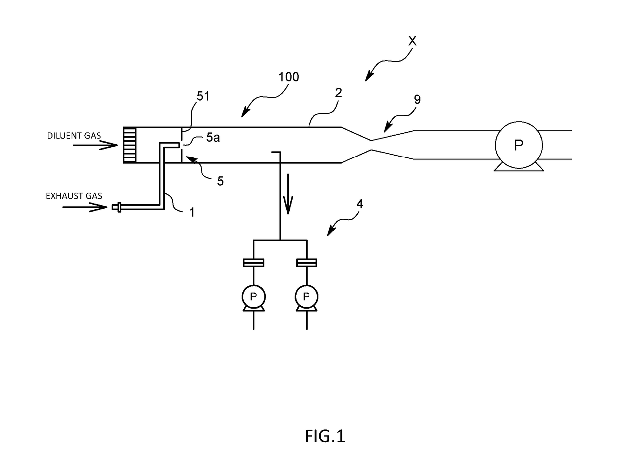
[0031]As illustrated in FIG. 1, an exhaust gas dilution device 100 according to the present embodiment is one of a full flow dilution type, and used as part of an exhaust gas measuring system X.

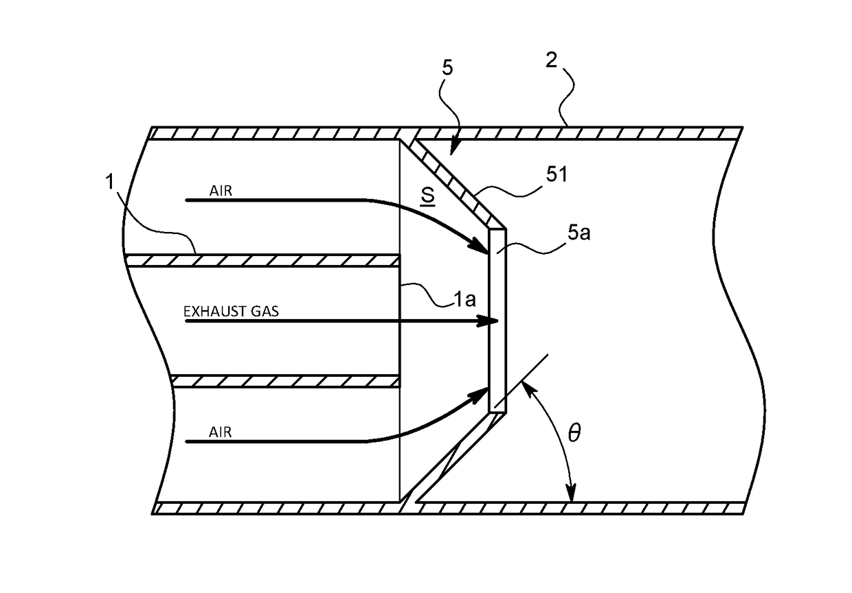
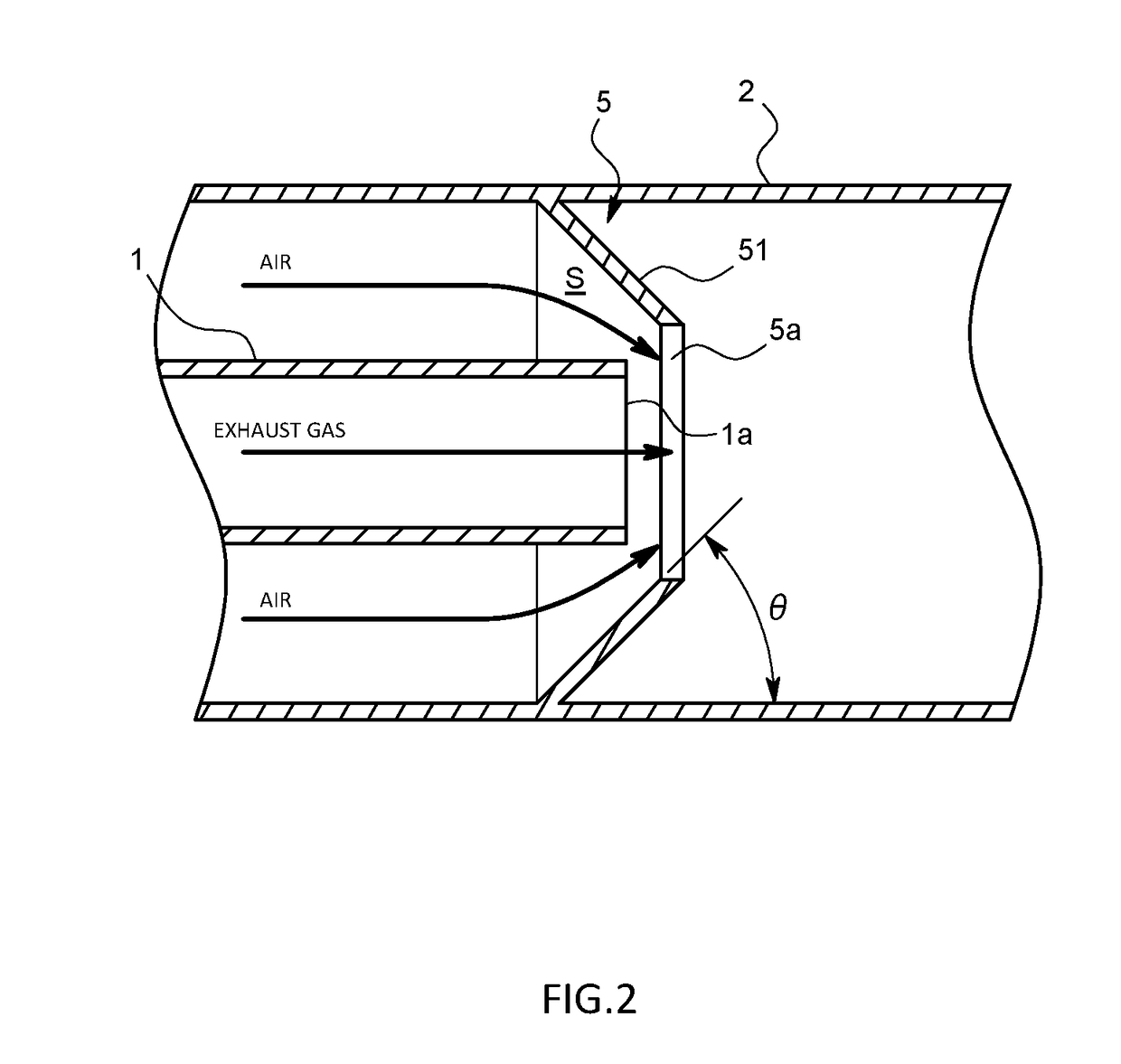
[0032]Specifically, the exhaust gas dilution device 100 includes: an exhaust gas sampling pipe 1 that is connected to an exhaust pipe (not illustrated) of an internal combustion engine and into which the total amount of exhaust gas is introduced; a circular pipe-shaped dilution tunnel 2 (hereinafter also simply referred to as a tunnel 2) as a dilution pipe into which the exhaust gas is introduced through the exhaust gas sampling pipe 1 and also air as diluent gas is introduced to mix them for diluting the exhaust gas; and a flow rate control device (CVS) 9 that makes the flow rate of mixed gas flowing through the tunnel 2 constant.

[0033]Note that numeral 4 in the diagram represents an ...


PUM


Abstract

In order to provide an exhaust gas dilution device capable of making a flow rate range wider than before, the exhaust gas dilution device is adapted to include a dilution tunnel through which diluent gas such as air flows, an orifice member adapted to block the dilution tunnel except for an orifice hole provided in a central part, and an exhaust gas introduction pipe 1 of which a discharge port is disposed so as to face to the orifice hole and face to a downstream side and through which exhaust gas is discharged from the discharge port into the dilution tunnel. In addition, in the exhaust gas dilution device, the orifice member is formed with a concave part that is gradually concaved from an outer circumferential edge part toward the orifice hole as viewed from an upstream side.

Description

CROSS-REFERENCE TO RELATED APPLICATION[0001]This application claims priority to JP Application No. 2015-241509, filed Dec. 10, 2015, the disclosure of which is incorporated in its entirety by reference herein.TECHNICAL FIELD[0002]The present invention relates to an exhaust gas dilution device adapted to dilute exhaust gas discharged from an internal combustion engine or the like for the purpose such as the component analysis of the exhaust gas, and to an exhaust gas measuring system using the exhaust gas dilution device.BACKGROUND ART[0003]When analyzing the components of exhaust gas of an internal combustion engine, the exhaust gas causes condensation or the like as it is to affect the analysis, and therefore after being diluted with diluent gas such as air, is introduced into an analytical instrument. A device to be used for the dilution is a full flow dilution device using a full tunnel or a partial dilution device using a micro tunnel.[0004]For example, taking the full flow dilu...

Claims


Application Information

Patent Timeline
Patent Type & Authority Applications(United States)
IPC IPC(8): F01N11/00F01N13/08G01M15/10F01N13/00
CPCF01N11/007F01N13/008F01N2550/14G01M15/102F01N13/082G01N1/2252G01N2001/2255
Inventor KUMAGAI, TATSUKI
Owner HORIBA LTD
Why Eureka
Try Eureka