System and method for dynamic control of a heat exchanger

Inactive Publication Date: 2017-06-15
ALFA LAVAL CORP AB
View PDF7 Cites 100 Cited by
  • Summary
  • Abstract
  • Description
  • Claims
  • Application Information

AI Technical Summary

Benefits of technology

[0015]The object of the present invention is to provide an improved heat exchanger system remedying the problems mentioned above. Especially it is aimed at a heat exchanger system and a method which a

Problems solved by technology

There is always a risk that the energy content of the supplied fluid is too high, whereby a part of the flow supplied to the inlet channel via its inlet port will meet the rear end of the inlet channel and be reflected thereby in the opposite direction.
Thereby the flow in the inlet channel is very chaotic and hard to predict and control.
In fact, it is sufficient that there is one malfunctioning first plate interspace for insufficient evaporation of the evaporator as a whole to occur.
Any droplets remaining in the evaporated fluid when reaching the inlet of the c

Method used


Image

  • System and method for dynamic control of a heat exchanger
  • System and method for dynamic control of a heat exchanger
  • System and method for dynamic control of a heat exchanger

Examples


Embodiment Construction

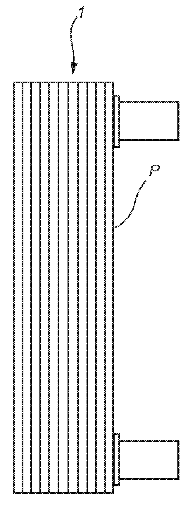
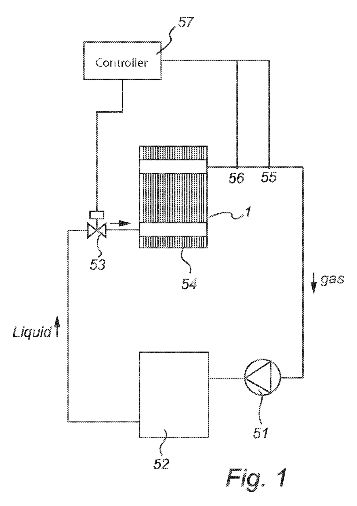
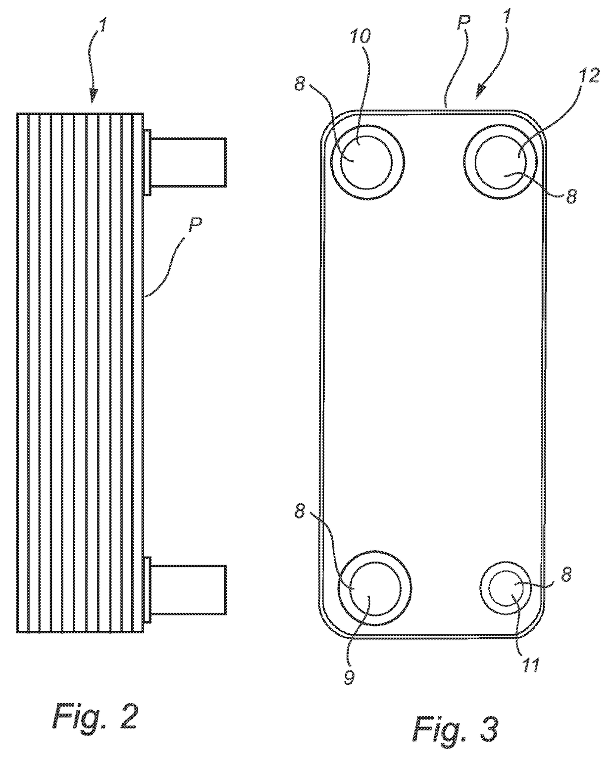
[0075]A heat exchanger 1 may typically be included as an evaporator in a refrigeration circuit. A prior art refrigeration system, see FIG. 1, being a mechanical vapor compression system, typically comprises a compressor 51, a condenser 52, an expansion valve 53 and an evaporator 54. The circuit may further comprise a pressure sensor 55 and a temperature sensor 56 arranged between the outlet of the evaporator and the inlet of the compressor. The refrigeration circle of such system starts when a cooling agent enters the compressor 51 in evaporated form with a low pressure and with a low temperature. The cooling agent is compressed by the compressor 51 to a high pressure and high temperature evaporated state before entering the condenser 52. The condenser 52 precipitates the high pressure and high temperature gas to a high temperature and high pressure liquid by transferring heat to a lower temperature medium, such as water or air. The high temperature liquid then enters the expansion ...


PUM


Abstract

The present application relates to a system for dynamic control of the operation of a heat exchanger, the system comprising a heat exchanger, a plurality of injector arrangements, a local sensor arrangement, and a controller, wherein the local sensor arrangement comprises a plurality of local temperature sensors being arranged to measure temperature values; and wherein the controller is arranged to determine a difference between the measured temperature values and is further arranged to communicate with the valves of the plurality of injector arrangements to adjust the local amount of first fluid supplied by at least one of the injector arrangements in order to even out the determined difference. The application also relates to a method for the dynamic control of the operation of a heat exchanger in such a system.

Description

TECHNICAL FIELD[0001]The present invention refers generally to a system for dynamic control of the operation of a heat exchanger. Further, the invention refers to a method for dynamic control of the operation of a heat exchanger.BACKGROUND ART[0002]The present invention refers generally to a system comprising a heat exchanger and in particular to a heat exchanger in the form of a plate heat exchanger. Different types of heat exchangers are based on different techniques. One type of heat exchanger utilizes evaporation of a fluid, such as a cooling agent, for various applications, such as air conditioning, cooling systems, heat pump systems, etc. Thus, the heat exchanger may be used in a two-phase system handling a fluid in a liquid form as well as in an evaporated form.[0003]In case of the evaporator being a plate heat exchanger, this may include a plate package, which comprises a number of first and second heat exchanger plates. The plates are permanently joined to each other and ar...

Claims


Application Information

Patent Timeline
IPC IPC(8): F28F27/02F25B41/06F28F9/02F25B39/00
CPCF28F27/02F25B39/00F25B41/062F25B2700/21175F25B39/028F25B2341/0661F25B2700/197F28F9/0273F28F9/026F28F9/027F28F27/00F28D9/005F25B41/385F25B41/34Y02B30/70
Inventor NYANDER, ANDERSBERTILSSON, KLASZORZIN, ALVARO
Owner ALFA LAVAL CORP AB
Why Eureka
Try Eureka