Locking pliers

a technology of locking pliers and pliers, which is applied in the field of hand tools, can solve the problems of high production cost of precious castings, and weak supporting rigidity of connecting rods, and achieve the effects of reducing the gripping force generated at the gripping head, improving the supporting rigidity of the connecting rod, and improving the gripping rigidity

Inactive Publication Date: 2017-06-22
HANGZHOU GREAT STAR TOOLS +1
View PDF4 Cites 2 Cited by
  • Summary
  • Abstract
  • Description
  • Claims
  • Application Information

AI Technical Summary

Benefits of technology

[0032]The pair of locking pliers of the present invention can grip all kinds of workpieces regardless of their sizes, as long as the sizes are not bigger than the maximum distance between the two gripping heads of the locking pliers, and there is no need to pre-adjust the distance between the gripping heads to accommodate the sizes of different workpieces. The accommodation to workpieces with different sizes mainly depends on the moving distance of the sliding block on the guide rod.
[0033]The connecting rod of the locking pliers of the present invention is a single connecting rod with one end connected to the handle and the other end connected to the sliding mechanism, and the connecting rod is made of high-strength materials, which can improve the supporting rigidity of the connecting rod.
[0034]The match between the adjusting mechanism and the connecting rod can adjust the gripping force between the gripping heads. When the interaction between the adjusting mechanism and the connecting rod occurs earlier, which means that after the adjusting mechanism of the present invention moves towards the gripping head, the initial angle between the second handle and the connecting rod turns bigger when the locking begins, therefore the gripping force generated at the gripping head will also be increased. When the interaction between the adjusting mechanism and the connecting rod occurs later, which means t

Problems solved by technology

It can be seen from the description of the above patents that intermediate connecting rods of the arm and the cam exist between the force input point on the handle and the locking element to achieve the locking, which lead to weak supporting rigidity.
But high producing precision needs precious casting, while the production cost of precious casting is high.
During the assembling process of locking pliers, except the locking block, which can be rapidly penetrated by the guide rod, the other components such a

Method used


Image

  • Locking pliers
  • Locking pliers
  • Locking pliers

Examples


Embodiment Construction

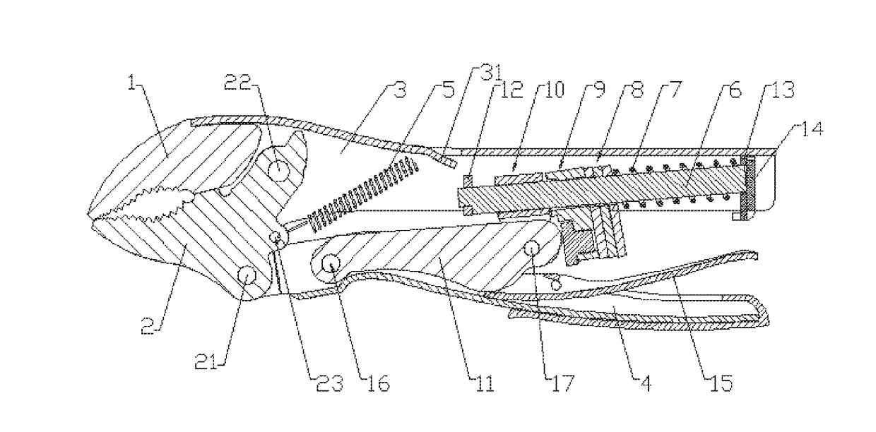
[0053]As shown in FIG. 1, in one embodiment of the locking pliers of the present invention, the locking pliers comprises a first gripping head 1, a second gripping head 2, a first handle 3 and a second handle 4. The first gripping head 1 is fixedly mounted to the first handle 3. The second gripping head 2 is roughly an L shape, which is mounted to the second handle 4 via a first joint 21 located at the turning point of the L shape, while one arm of the L shape of the second gripping head 2 is further mounted to the first handle 3 via a fourth joint 22. The second gripping head 2 is mounted to the second handle 4 via a rivet at the first joint 21 and to the first handle 3 via a rivet at the fourth joint 22. The second gripping head 2 can pivot around the first joint 21 relative to the second handle 4 and can also pivot around the fourth joint 22 relative to the first handle 3.

[0054]A hole 23 is arranged between the first joint 21 and the fourth joint 22 of the second gripping head 2,...


PUM


Abstract

An example pair of locking pliers comprises a first gripping head, a second gripping head, a first handle and a second handle, the first gripping head being mounted to the first handle, the second gripping head being pivotably mounted to the first handle and pivotably mounted to the second handle via a first joint. The pair further comprises a single connecting rod, a sliding mechanism and a locking mechanism, one end of the connecting rod mechanism being pivotably mounted to the second handle via a second joint, the other end being pivotably mounted to the sliding mechanism via a third joint, the sliding mechanism and the locking mechanism being slidably mounted to the first handle.

Description

CROSS REFERENCE TO RELATED APPLICATIONS[0001]The present application is a national stage entry of the PCT Patent Application No. PCT / CN2014 / 082493, filed Jul. 18, 2014, which is hereby incorporated by reference in its entirety.TECHNICAL FIELD[0002]The present application relates to a hand tool, particularly to a pair of locking pliers.DESCRIPTION OF THE PRIOR ART[0003]Locking pliers are mainly used for gripping parts so as to process the parts, such as gripping parts for processing of riveting, welding, grinding and the like. Compared with ordinary pliers, the jaw of locking pliers can generate greater gripping force so that the processing will not be influenced by looseness of the parts. Furthermore, locking pliers can also be used as wrench.[0004]Ordinary pliers generally include pliers head and handles. The force acting on handles is changed into greater acting force on pliers head via a transition of lever principle. But once the force acting on the handles disappears, the jaws ...

Claims


Application Information

Patent Timeline
IPC IPC(8): B25B7/12
CPCB25B7/123
Inventor WANG, MIN
Owner HANGZHOU GREAT STAR TOOLS
Why Eureka
Try Eureka