
In Situ Biomass Generator with Automated Disinfection

a biomass generator and automatic disinfection technology, applied in the direction of biomass after-treatment, specific use bioreactors/fermenters, apparatus sterilization, etc., can solve the problems of large energy consumption, complex temperature, pressure and mixing systems requiring substantial capital investment, etc., to facilitate automatic cleaning of wetted portions, improve product quality, and prolong service intervals

Inactive Publication Date: 2017-06-22
NCH CORP
View PDF2 Cites 9 Cited by
  • Summary
  • Abstract
  • Description
  • Claims
  • Application Information

AI Technical Summary

Benefits of technology

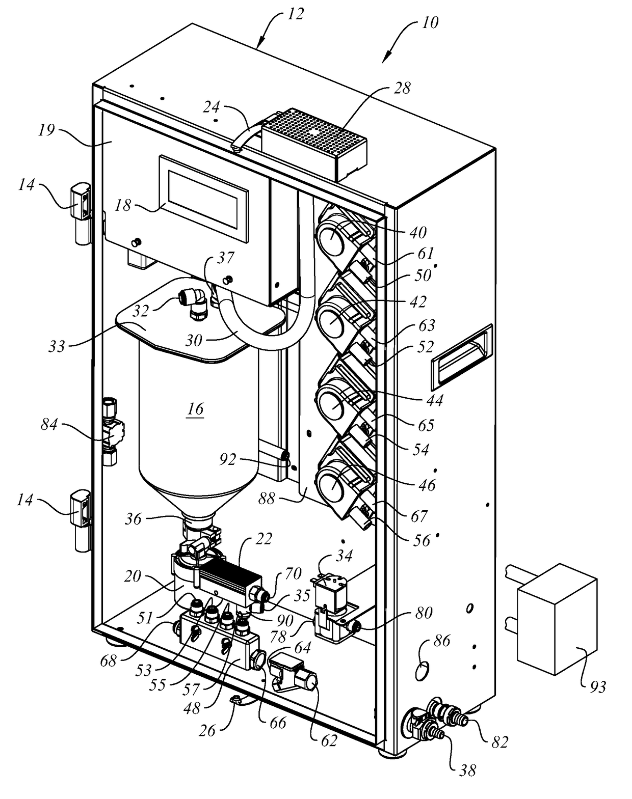
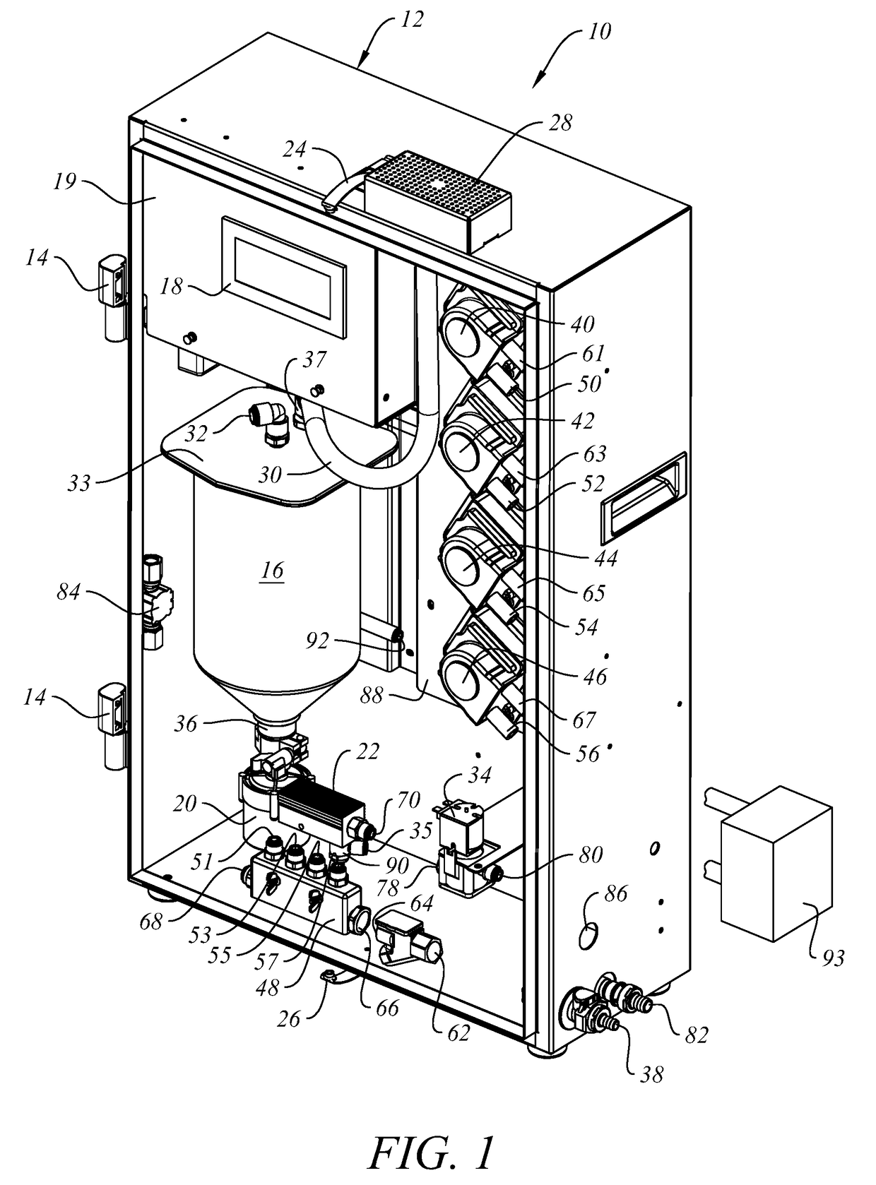
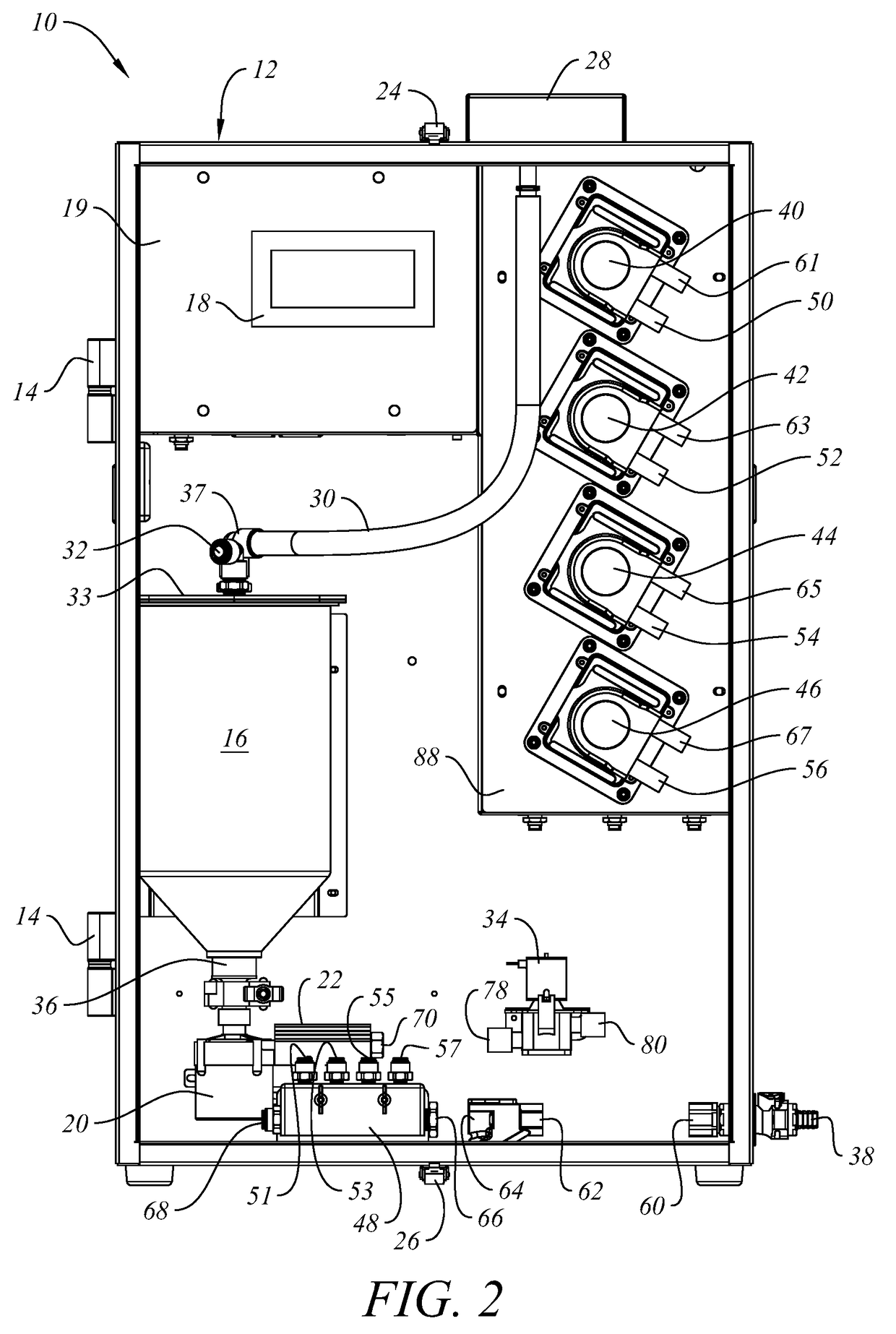
The patent describes a system and apparatus for growing bacteria that have the capability to automatically clean themselves after each growing cycle without the need for a service technician. The system includes an in situ biomass generator with a sanitizer or disinfectant included inside, along with a minimum footprint and scalability for larger volumes. The apparatus features precision liquid controls and low energy requirements and can be operated by solar, battery, or direct electrical power. The technical effects of this patent include improved product quality, longer service intervals, lower operating costs, and a unique flow design that reduces the likelihood of film or solids accumulation inside the apparatus.

Problems solved by technology

Such systems are often designed and implemented on an industrial scale, with a large footprint, complex temperature, pressure and mixing systems requiring substantial capital investment, significant energy demands, offsite utilities, and highly trained operators and maintenance personnel.
Such devices are disclosed, for example, in U.S. Pat. Nos. 6,335,191; 7,081,361; 7,635,587; 8,093,040; and 8,551,762, but typically lack clean in place (CIP) functionality and require some disassembly in order to clean and disinfect the interior surfaces of component parts such as vessels, flow lines, valves and pumps.

Method used


Image

  • In Situ Biomass Generator with Automated Disinfection
  • In Situ Biomass Generator with Automated Disinfection
  • In Situ Biomass Generator with Automated Disinfection

Examples


example 1

[0057]Using the system and apparatus of the invention as disclosed here in one satisfactory mode of operation, a liquid disinfection agent or mixture of disinfection agents is automatically dispensed into the biomass generator mixing manifold, flushed into the growth chamber with 80% of full water charge, and allowed to circulate for a pre-determined time. The circulation is then interrupted; the remaining fermentation components are introduced into the mixing manifold, and the remaining 20% of full water charge is used to flush the bacteria growth components through the system and in the mixing vessel. The mixing vessel circulation is then restarted and normal the normal bacteria growth (fermentation) process continues. At the completion of the biomass fermentation process, the fermentation liquid is dispensed. A rinse cycle process is initiated by injecting a small amount of disinfecting agent into the mixing manifold which is flushed into the system and mixing vessel with a 30% o...

example 2

[0072]Tap water and about 10 mL Bacillus spore suspension, 60 mL nutrient broth and 5 mL defoamer are added per about 3 liters water to form a bacteria growth medium, which is then heated to raise the temperature of the medium to about 65° C. The heated growth medium is recirculated through the growth chamber and a heater (preferably part of the subject system but disposed external to the housing containing the bacteria growing chamber) for about one hour while maintaining the liquid temperature at about 65° C., after which the heater is turned off and the flow of recirculating growth medium is redirected to bypass the heater. Recirculation continues until the bacteria growth medium cools to a temperature of about 35° C., at which time an electronic timer initiates timing of a predetermined bacteria growth cycle. At the end of the bacteria growth cycle, the bacteria growth medium is harvested through the drain tube, and another cycle of operation can begin.

[0073]Alternatively, in ci...


PUM

PropertyMeasurementUnit
temperatureaaaaaaaaaa
volumesaaaaaaaaaa

Abstract

A self-contained biomass generator configured for use in growing and discharging bacteria at or near an intended use site and having a housing containing a bacteria growth chamber; water and air inlets; receptacles and solenoid pumps for liquids containing bacteria spores, nutrient, defoamer and disinfectant; a recirculation pump; air pump; water heater; manifold; a dosing pump configured to dispense controlled amounts of bacteria; and a programmable electronic controller configured to operate the device through a plurality of bacteria growth cycles and to disinfect the wetted internal surfaces between growth cycles without requiring service or operator intervention. A process for using the biomass generator is also disclosed.

Description

BACKGROUND OF THE INVENTION[0001]1. Field of the Invention[0002]This invention relates to biomass generators that grow and discharge bacteria for beneficial end uses such as remediation of contaminates, control of pests, production of micro-organisms, and reduction of odors. More particularly, this invention relates to an in situ bacteria production system and apparatus configured to grow utility populations of probiotic bacteria suitable for use with animals, in animal feeds, and in water supplies to promote overall health and metabolic efficiency. As used throughout this disclosure, “in situ” refers to biomass generators in which utility populations of useful bacteria that are sufficient for a particular application are grown at or near the intended use site. The invention also relates to an in situ bacteria production system and apparatus that is configured to filter air introduced into the apparatus and to automatically sanitize or disinfect the apparatus between bacteria growth...

Claims


Application Information

Patent Timeline
Patent Type & Authority Applications(United States)
IPC IPC(8): C12M1/12C12M1/36C12M1/34C12M1/00
CPCC12M37/00C12M23/40C12M29/20C12M41/48C12M41/12C12M29/00C12M29/18C12M29/26
Inventor BOYETTE, SCOTTBOESCH, WILLIAM P.ERDMAN, ALEXANDER C.RUSHING, MIKEPRUITT, JUDITH G.ABERLE, DANIELMCKINNON, ANDREW
Owner NCH CORP
Learn More