
Internal combustion engine having an engine backpressure brake and a compression release engine brake

Active Publication Date: 2017-06-22
MAN NUTZFAHRZEUGE AG
View PDF7 Cites 3 Cited by
  • Summary
  • Abstract
  • Description
  • Claims
  • Application Information

AI Technical Summary

Benefits of technology

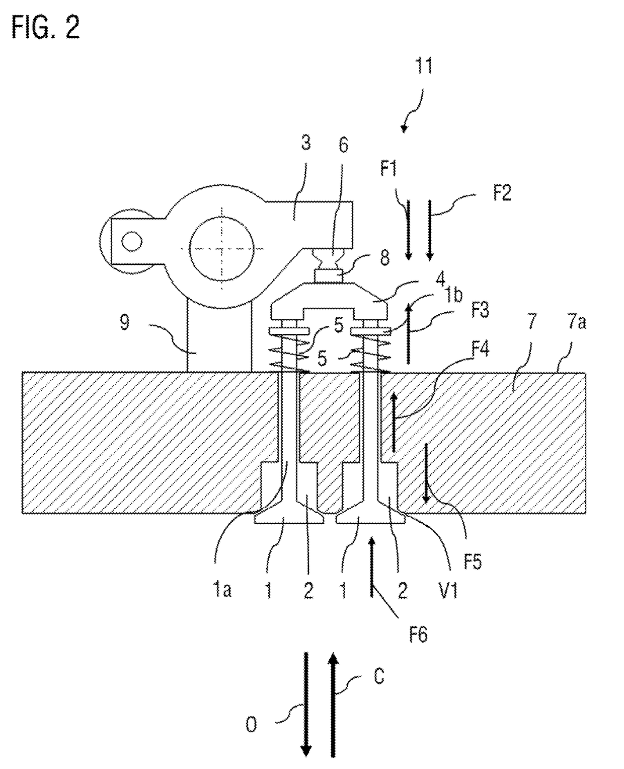
The present patent aims to provide an improved engine brake and automatic valve clearance compensation means in a simpler, less expensive, and more space-efficient manner. The hydraulic valve clearance compensation element is designed to act on the outlet valve in the engine braking mode, in which the forces act in opposite directions. The element assumes a double function, both as a maintenance-free valve train and as a compression release engine brake. The advantage of this design is that it saves components and costs. The patent also discusses measures to shift the engine speed limit towards greater values, such as reducing the exhaust gas pressure, increasing the gas pressure on the combustion chamber side, reducing the oil pressure, increasing the valve spring force, or increasing the friction in the valve train. Additionally, the patent suggests that a counterholder for opening the outlet opening of the relief line only at the beginning of the outlet stroke can be eliminated, saving costs.

Problems solved by technology

As a result of the numerous hydraulic pistons and pressure lines which are arranged in the valve crosshead, high machining and manufacturing complexity of the valve crosshead is required, the valve crosshead being weakened structurally and therefore having to be of correspondingly solid design.
In this type of engine braking devices, the use of hydraulic valve clearance compensation devices requires additional measures, in order to avoid uncontrolled pumping up of the valve clearance compensation device during the engine braking mode, which might lead to serious engine damage.
The arrangement which is known from the prior art with numerous oil bores and hydraulic pistons in the valve crosshead has the disadvantage that the valve crosshead is weakened structurally and therefore has to be of greater dimensions.
Furthermore, the internal combustion engine includes an engine speed limiting device which is configured to deactivate an injection of fuel above a predetermined cut-off engine speed.
This saves components and costs.

Method used


Image

  • Internal combustion engine having an engine backpressure brake and a compression release engine brake
  • Internal combustion engine having an engine backpressure brake and a compression release engine brake
  • Internal combustion engine having an engine backpressure brake and a compression release engine brake

Examples


Embodiment Construction

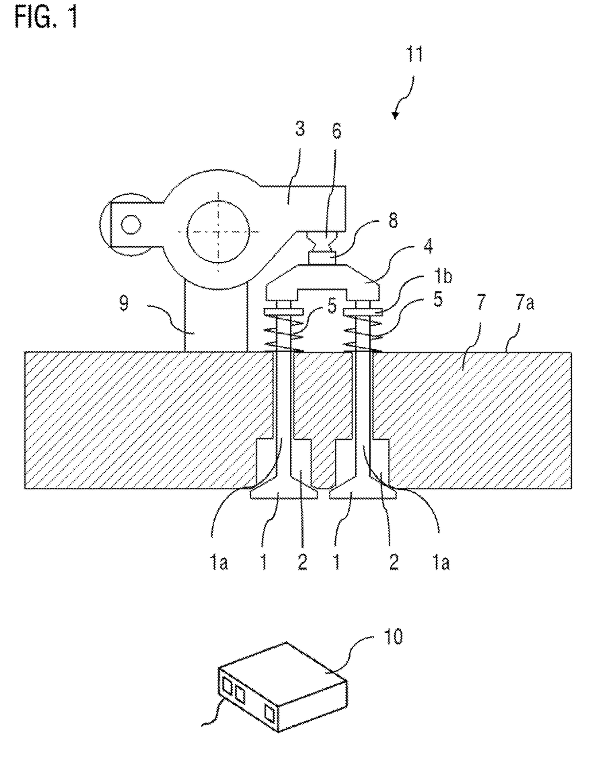
[0040]It is known in general to protect an internal combustion engine against impermissibly high engine speeds by way of the installation of an engine speed limiting device. Engine speed limiting is achieved by switching off the injection of fuel above a predetermined maximum engine speed. To this end, there is a corresponding control function in the respective injection controller. In the present case, the internal combustion engine therefore comprises the engine speed limiting device 10 which is configured to deactivate an injection of fuel above a predetermined cut-off engine speed n1.

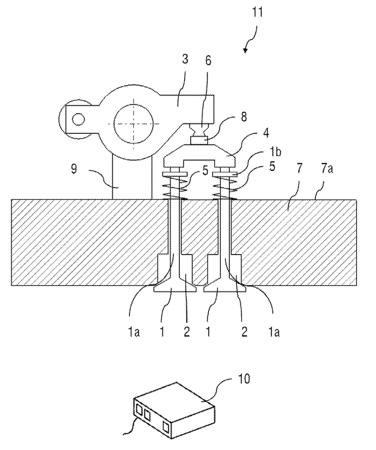
[0041]Furthermore, FIG. 1 shows a valve train 11 with a hydraulic valve clearance compensation means 6 of an internal combustion engine according to one embodiment of the present disclosure. The internal combustion engine comprises a 4-stroke reciprocating piston internal combustion engine (not shown) which has at least one inlet valve (not shown) and two outlet valves 1 per cylinder.

[0042]The inlet...


PUM


Abstract

An internal combustion engine having at least one outlet valve per cylinder, which can be actuated via a camshaft and a transmission device, a hydraulic valve clearance compensation element being arranged in the transmission device between the camshaft and the outlet valve, and having an engine braking device, having an engine backpressure brake for building up an exhaust gas backpressure and a compression release engine brake, by way of which at least one outlet valve can be held open at least in an engine braking phase, the compression release engine brake being formed by the hydraulic valve clearance compensation element.

Description

BACKGROUND[0001]1. Technical Field[0002]The present disclosure relates to an internal combustion engine having at least one outlet valve per cylinder, which outlet valve can be actuated via a camshaft and a transmission device, a hydraulic valve clearance compensation element being arranged in the transmission device between the camshaft and the outlet valve, and having an engine braking device, having an engine backpressure brake for building up an exhaust gas back pressure and a compression release engine brake, by way of which at least one outlet valve can be held open at least in an engine braking phase.[0003]2. Discussion of Related Art[0004]Laid open specifications EP 2 143 894 A1 and EP 2 143 896 A1 have disclosed internal combustion engines having engine braking devices and valve clearance compensation mechanisms. Here, in each case one hydraulic valve clearance compensation mechanism is arranged in a valve crosshead. Here, the valve clearance compensation mechanism has a pi...

Claims


Application Information

Patent Timeline
IPC IPC(8): F01L13/06F02D13/04F02D13/06F02D17/02
CPCF01L13/06F02D13/06F02D13/04F02D17/02F01L1/2422F01L1/26F02D13/0242F02D13/0276F02D31/009F02D41/30B60W10/198F01L1/181F01L1/2411F02D9/06F01L1/24F01L1/18
Inventor EBERT, CHRISTOPHHERRMANN, TOBIASFINK, ADRIAN
Owner MAN NUTZFAHRZEUGE AG
Learn More