
System and method for velocity selective pulses with arbitrary shape using MRI

a selective pulse and velocity technology, applied in the field of medical imaging, can solve the problems of sensitivity to b1 inhomogeneity, the original scheme (without refocusing pulses) suffers from off-resonance effect, and the tolerable b0 offset is limited to 80 hz

Active Publication Date: 2017-06-22
THE JOHN HOPKINS UNIV SCHOOL OF MEDICINE
View PDF4 Cites 2 Cited by
  • Summary
  • Abstract
  • Description
  • Claims
  • Application Information

AI Technical Summary

Benefits of technology

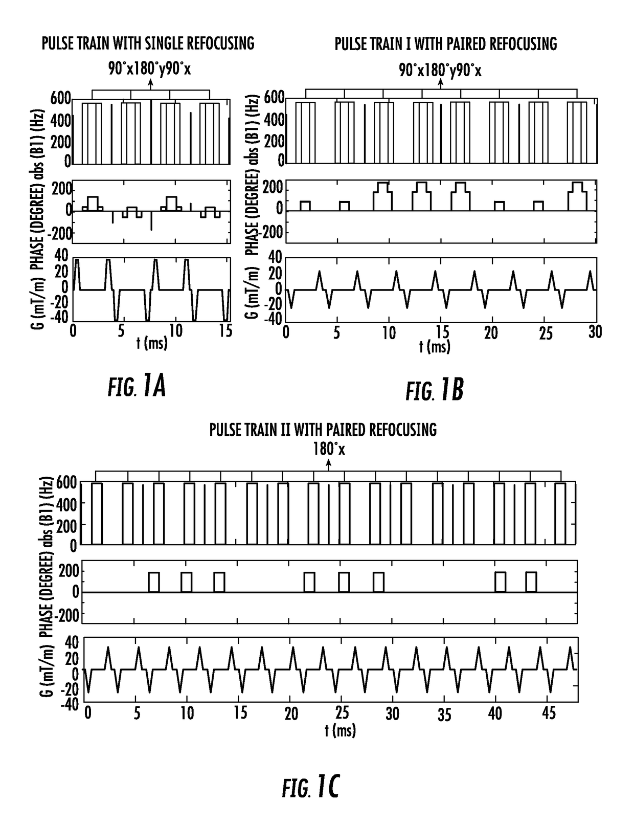
The present invention is a method for getting magnetic resonance images or spectra of a subject using a special scan technique called velocity-selective pulse train. This technique includes embedding a pair of refocusing pulses in each velocity encoding step of the scan. The refocusing pulses can be in the form of adiabatic pulses, and each velocity encoding step includes a pair of refocusing pulses. The velocity-selective pulse train can also include gradient lobes with the pair of refocusing pulses embedded among them. The technical effect of this invention is to improve the accuracy and quality of magnetic resonance imaging scans and to provide a better understanding of the underlying mechanisms of brain function.

Problems solved by technology

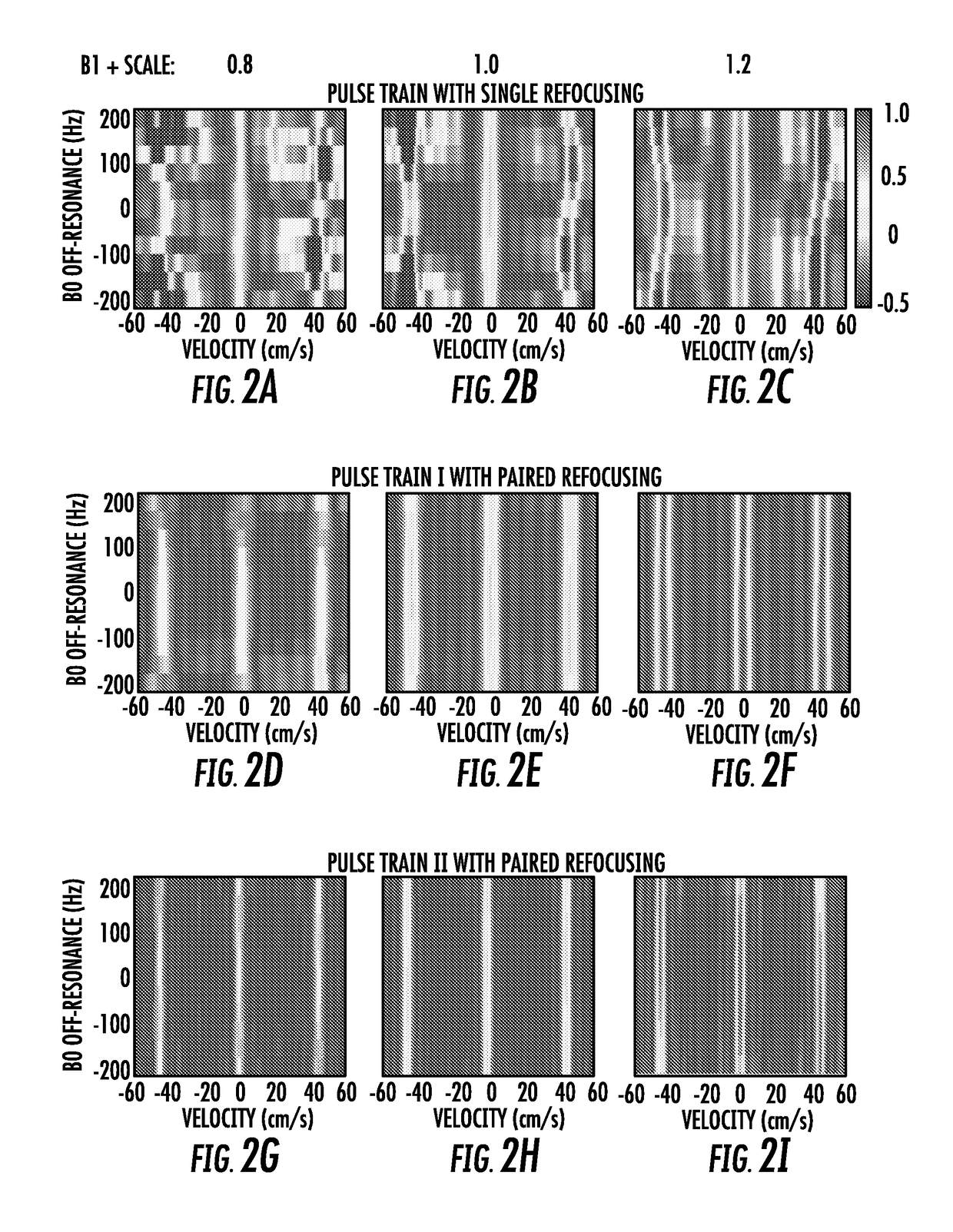
However, the original scheme (without refocusing pulses) suffers from off-resonance effect which is manifested as excitation profile shifting along velocity.
The susceptibility to B0 field inhomogeneity can be alleviated, by incorporating one composite refocusing pulse within each velocity encoding step and modifying the RF and gradient waveforms accordingly, as recently shown for peripheral MRA at 1.5 T. However, the tolerable B0 offset is limited to ±80 Hz and the sensitivity to B1 inhomogeneity remains an issue particularly at high field strength.
Unfaithful B1+ scale (ratio of actual flip angle to nominal input flip angle) leads to two independent consequences: incorrect RF weighting for the excitation k-space by the hard pulse at the beginning of each velocity encoding step and thus inaccurate flip angle for either the inversion or saturation band; imperfect refocusing during each velocity encoding step and thus degraded velocity selective profile at off-resonance.

Method used


Image

  • System and method for velocity selective pulses with arbitrary shape using MRI
  • System and method for velocity selective pulses with arbitrary shape using MRI
  • System and method for velocity selective pulses with arbitrary shape using MRI

Examples


Embodiment Construction

[0015]The presently disclosed subject matter now will be described more fully hereinafter with reference to the accompanying Drawings, in which some, but not all embodiments of the inventions are shown. Like numbers refer to like elements throughout. The presently disclosed subject matter may be embodied in many different forms and should not be construed as limited to the embodiments set forth herein; rather, these embodiments are provided so that this disclosure will satisfy applicable legal requirements. Indeed, many modifications and other embodiments of the presently disclosed subject matter set forth herein will come to mind to one skilled in the art to which the presently disclosed subject matter pertains, having the benefit of the teachings presented in the foregoing descriptions and the associated Drawings. Therefore, it is to be understood that the presently disclosed subject matter is not to be limited to the specific embodiments disclosed and that modifications and other...


PUM


Abstract

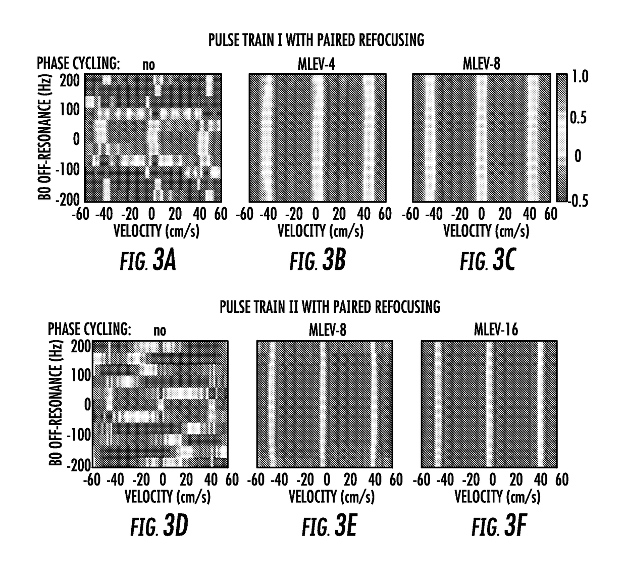
The present invention is directed to a system and method for magnetic resonance imaging including an extended Fourier transform-based velocity-selective pulse train design with a pair of refocusing pulses within each velocity encoding step and accompanying phase cycling between different velocity encoding steps. The present invention is robust to B0 / B1 field inhomogen-city and eddy current effects. The utility of this technique, through a velocity-selective inversion pulse, is demonstrated in a 2D velo-city-selective arterials spin labeling study, which shows a reasonable agreement in CBF quantification with the standard PCASL method.

Description

CROSS REFERENCE TO RELATED APPLICATIONS[0001]This application claims the benefit of U.S. Provisional Patent Application Nos. 61 / 981,431 filed Apr. 18, 2014 and 61 / 991,657 filed May 12, 2014, each of which are incorporated by reference herein, in their entirety.GOVERNMENT SUPPORT[0002]The present invention was made with government support under grant number NIH K25 HL121192 and P41 EB015909 awarded by the National Institutes of Health. The government has certain rights in the present invention.FIELD OF THE INVENTION[0003]The present invention relates generally to medical imaging. More particularly, the present invention relates to a system and method for velocity selective pulses using MRI.BACKGROUND OF THE INVENTION[0004]Velocity-selective (VS) pulse trains can provide unique functionalities when designing pulse sequences for various Magnetic Resonance Imaging (MRI) based hemodynamic evaluation: MR angiography (MRA); blood flow (perfusion), blood volume, or transit time; oxygen extr...

Claims


Application Information

Patent Timeline
Patent Type & Authority Applications(United States)
IPC IPC(8): G01R33/563A61B5/145A61B5/026G01R33/565A61B5/055
CPCG01R33/56308G01R33/5635G01R33/56518A61B5/14542G01R33/5659A61B5/055A61B5/0263G01R33/56563
Inventor QIN, QINVAN ZIJL, PETER
Owner THE JOHN HOPKINS UNIV SCHOOL OF MEDICINE
Learn More