X-ray analyzing apparatus

a technology of x-ray analyzing and x-ray, which is applied in the direction of instruments, measurement devices, scientific instruments, etc., can solve the problems of unstable within a range of approximately several percent, inability to perform accurate analysis, and sudden lowering of pulse height to be sent to the pulse height analyzer, etc., to achieve the effect of performing accurate analysis in a short tim

Active Publication Date: 2017-06-29
RIGAKU CORP
View PDF2 Cites 10 Cited by
  • Summary
  • Abstract
  • Description
  • Claims
  • Application Information

AI Technical Summary

Benefits of technology

[0014]Therefore, an object of the present invention is to provide an X-ray analyzing apparatus capable of correcting, even when peak shift occurs, the peak shift speedily and appropriately, and performing accurate analysis in a short time.

Problems solved by technology

However, it has been known that, for example, in a case where a proportional counter is used as the detector, when high-intensity fluorescent X-rays are incident on the detector, a pulse voltage, that is, a pulse height to be sent to the pulse height analyzer may be suddenly lowered by several tens percent in a several seconds, and further, may be unstable within a range of approximately several percent for next ten and several minutes.
When peak shift occurs, measurement is performed using an inappropriately set window which is shifted from a target wavelength, and thus, accurate analysis is impossible (see Patent Documents 1 to 4).
This problem may also occur in X-ray analyzing apparatuses other than wavelength dispersive X-ray fluorescence spectrometers, and may also occur, which varies in degree, when detectors other than proportional counters are used (see Patent Documents 3 and 4).
This makes accurate analysis impossible.
In a case where a pulse height is unstable for ten and several minutes after being suddenly lowered, performing accurate analysis in a short time is more difficult.
On the other hand, in the second conventional technology, when an X-ray intensity suddenly changes, or an interfering line (for example, a secondary or higher order reflection line for X-rays to be analyzed) is included in an energy spectrum, the peak position may be incorrectly detected.
In this case, accurate analysis is impossible.

Method used


Image

  • X-ray analyzing apparatus
  • X-ray analyzing apparatus
  • X-ray analyzing apparatus

Examples


Embodiment Construction

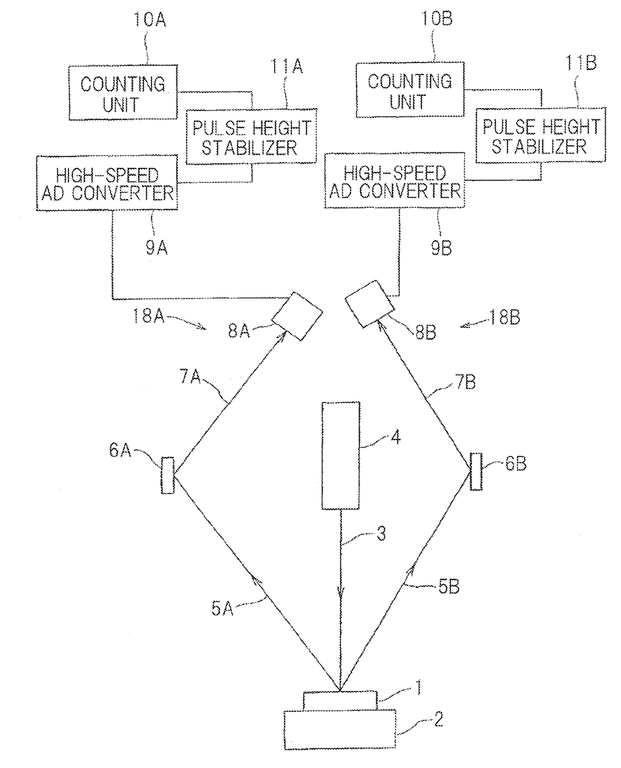
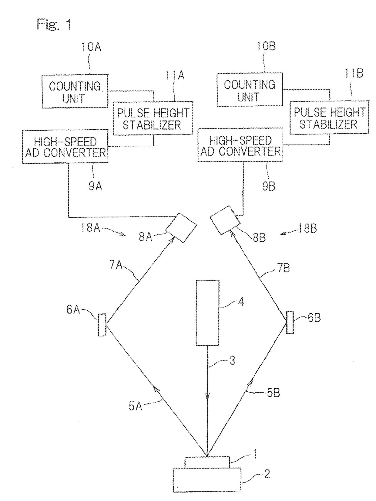
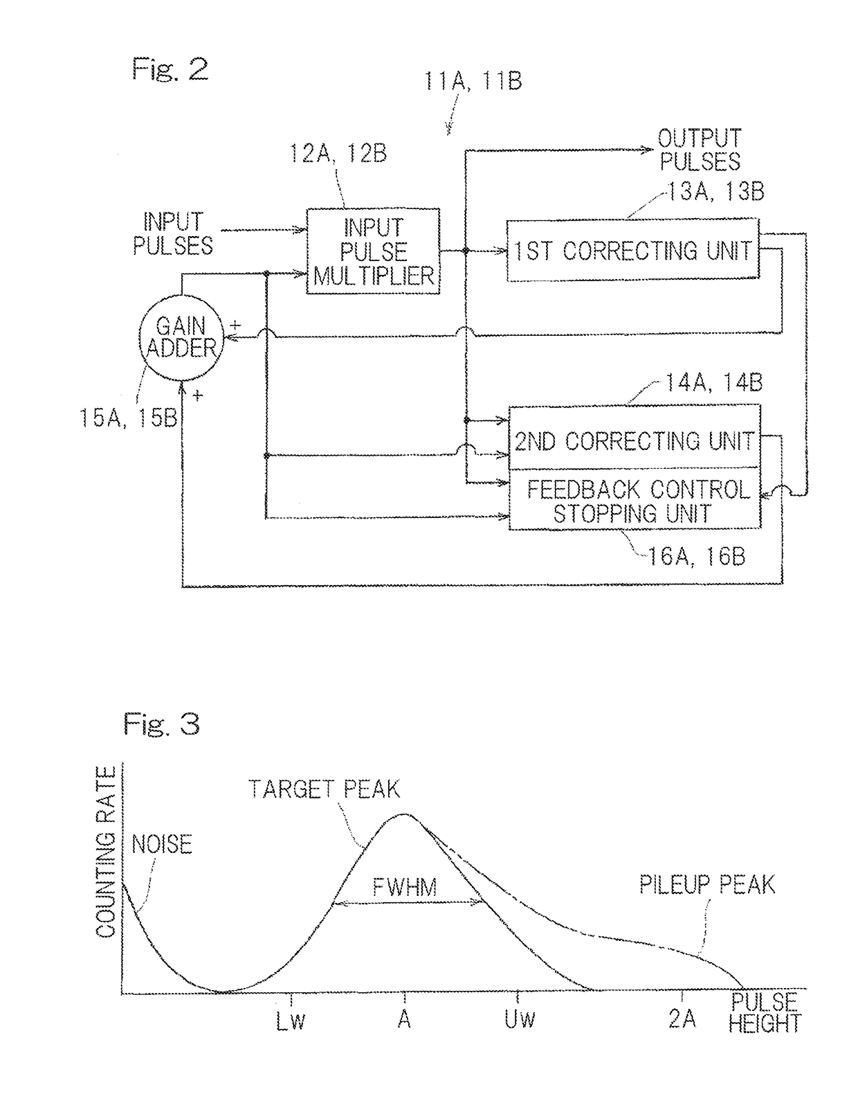
[0029]Hereinafter, a wavelength dispersive X-ray fluorescence spectrometer according to an embodiment of the present invention will be described with reference to the drawings. As illustrated in FIG. 1, the spectrometer includes detection units 18A, 18B provided for the respective wavelengths of secondary X-rays 7A, 7B such as fluorescent X-rays to be measured. The detection units 18A, 18B include spectroscopic devices 6A, 6B, detectors 8A, 8B, high-speed AD converters 9A, 9B, pulse height stabilizers 11A, 11B, and counting units 10A, 10B, respectively. This X-ray fluorescence spectrometer is a wavelength dispersive type and a simultaneous multi-elements analysis type. Preamplifiers may be provided between the detectors 8A, 8B and the high-speed AD converters 9A, 9B, respectively.

[0030]More specifically, the spectrometer includes: a sample table 2 on which a sample 1 is placed; an X-ray source 4 which is an X-ray tube configured to irradiate the sample 1 with primary X-rays 3; the s...


PUM

PropertyMeasurementUnit
speedaaaaaaaaaa
heightaaaaaaaaaa
spectrumaaaaaaaaaa

Abstract

The X-ray analyzing apparatus according to the present invention includes, in combination: a first correcting unit (13A, 13B) to output a first gain to cause a pulse height of a target peak which is estimated on the basis of a sum of counting rates obtained in preliminary measurement, to match a predetermined expected pulse height; and a second correcting unit (14A, 14B) to output, in real time through feedback control, a second gain to be added to the first gain in order to cause the pulse height of the target peak detected within a predetermined energy range, to match the expected pulse height, and further includes a feedback control stopping unit (16A, 16B) to appropriately determine presence/absence of an interfering line with respect to the target peak, and to set, when determining that the interfering line exists, the gain to a fixed value including only the first gain.

Description

CROSS REFERENCE TO THE RELATED APPLICATION[0001]This application is a continuation application, under 35 U.S.C. §111(a), of international application No. PCT / JP2015 / 074270, filed Aug. 27, 2015, which claims priority to Japanese patent application No. 2014-190249, filed Sep. 18, 2014, the entire disclosure of which is herein incorporated by reference as a part of this application.BACKGROUND OF THE INVENTION[0002]Field of the Invention[0003]The present invention relates to an X-ray analyzing apparatus which corrects so-called peak shift.[0004]Description of Related Art[0005]In a conventional wavelength dispersive X-ray fluorescence spectrometer, a sample is irradiated with primary X-rays, a spectroscopic device monochromates fluorescent X-rays generated from the sample, a detector detects the monochromated fluorescent X-rays to generate pulses. A voltage of the pulse, that is, a pulse height corresponds to energy of the fluorescent X-rays, and specifically, is considered to be proport...

Claims


Application Information

Patent Timeline
Patent Type & Authority Applications(United States)
IPC IPC(8): G01N23/207G01N23/223G01T1/17
CPCG01T1/17G01N2223/303G01N2223/076G01N23/223G01T1/40G01N2223/304
Inventor SAKO, YUKIO
Owner RIGAKU CORP
Why Eureka
Try Eureka