Flat antenna for satellite communication

a satellite communication and antenna technology, applied in the direction of antennas, particular array feeding systems, coupling devices, etc., can solve the problems of limiting the number of directions in which the antenna can be pointed, affecting the pointing direction, and not allowing simultaneous operation in two very different frequency bands

Active Publication Date: 2017-06-29
INEO DEFENSE
View PDF0 Cites 1 Cited by
  • Summary
  • Abstract
  • Description
  • Claims
  • Application Information

AI Technical Summary

Benefits of technology

[0018]Thus, the invention makes it possible, by displacing the rotationally movable horn, to scan a large number of pointing directions associated with the radiating lines of the antenna. The tuning of each radiating line being performed through the length of a transmission line linking the array of sensors of the at least one metallic plate and the radiating board. The invention makes it possible to fix the antenna on a plane surface, thus limiting the fragility of the antenna and improving the aerodynamic shape of the carrier of the antenna. The antenna in accordance with the invention also eliminates the need for coaxial cables and for connectors. This antenna structure operates in a very broad frequency band since the horn allows frequency-independent pointing.
[0020]According to one embodiment, the length of the at least one transmission line is adapted so as to introduce an additional delay making it possible to obtain an initial fixed pointing in such a way that the total pointing varies from 0° to 60° for a symmetric displacement of the horn of about ±30°. This embodiment, associated with the 360° global rotation of the antenna about its axis z, makes it possible to contain all the directions in a cone of half-angle 60° centered on the direction normal to the antenna.
[0025]According to one embodiment, said radiating board comprises several radiating lines spaced apart by half a wavelength. This embodiment makes it possible in particular to avoid problems related to array lobes.

Problems solved by technology

However, the direction of the pointing in terms of a varies with the wavelength A and does not allow simultaneous operation in two very different frequency bands such as in the Satcom Ka band for example (20 GHz when receiving, 30 GHz when sending).
However, this solution limits the number of directions in which the antenna can be pointed as a function of the number of linear sources.
Moreover, the installation of a linear array of sources and means of electronic selection increases the bulkiness of the flat antenna.
Such an antenna poses production problems when the antenna is designed to operate in the Ku or Ka high-frequency bands.
Secondly, the size of the connectors of the coaxial cables limits the possibilities of installation and the number of usable horns.
Moreover, an antenna with a diameter of 500 mm operating at 30 GHz comprises about 100 cables, all different, this impacting negatively on the specifications and the steps of production.

Method used


Image

  • Flat antenna for satellite communication
  • Flat antenna for satellite communication
  • Flat antenna for satellite communication

Examples


Embodiment Construction

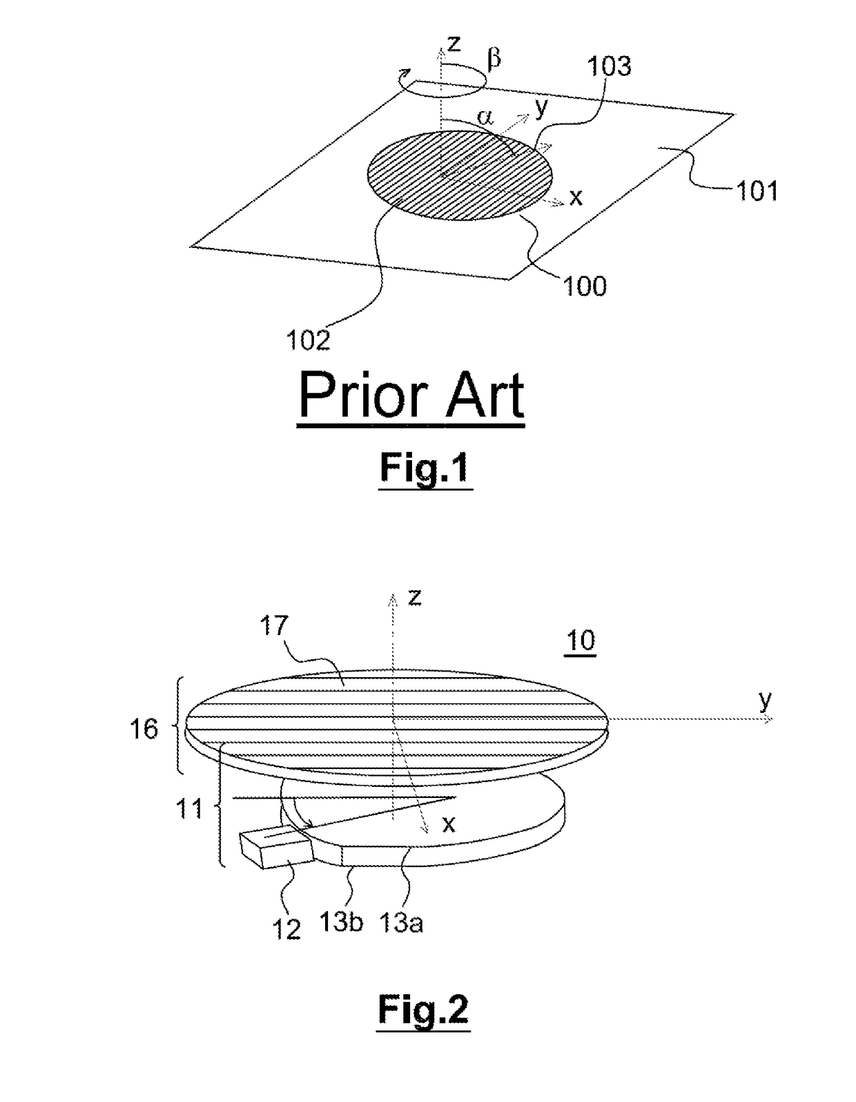
[0038]FIG. 2 reveals a flat satellite telecommunications antenna 10 consisting of a radiating board 16 linked to an adaptation means 11 able to modify the delays of the fields emitted or received by the radiating board 16.

[0039]The radiating board 16 extends in a plane xy and comprises several radiating lines 17 disposed along the axis y at a spacing of about half a wavelength along the axis x. Each radiating line 17 consists of an alignment of N radiating elements (not represented), for example dipoles, patches or slots disposed at a spacing of less than a wavelength along the y axis and fed by a distributor comprising one input and N outputs.

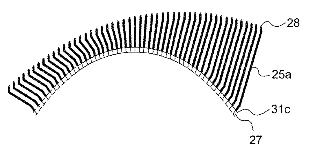
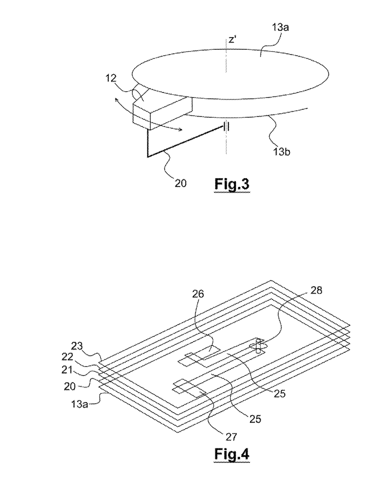
[0040]The adaptation means 11 consists of a horn 12 movable in rotation between two metallic plates 13a and 13b parallel to the radiating board 16. The horn 12, represented in FIG. 3, is movable in rotation about the axis z′ (parallel to or coincident with the axis z) extending in a direction normal to the plane xy. The mobility of the horn 12...


PUM


Abstract

A flat antenna for satellite communication includes a radiating board. The radiating board includes at least one radiating line, and an adapter configured to modify the delay of the fields transmitted or received by the radiating line. The adapter includes a horn mobile in rotation between the two metal plates, and a multilayer power supply circuit. The first layer of the multilayer power supply circuit is formed at least one metal plate containing an array of slot sensors and the last layer of the multilayer power supply circuit is provided with at least one coupling slot connected to the radiating line. The first layer and the last layer is linked by at least one transmission line. The length of the transmission line is suitable for introducing a delay required to focus the wave radiated by the radiating line.

Description

FIELD OF THE INVENTION[0001]The present invention pertains to the field of flat antennas for satellite telecommunications. The invention is particularly adapted for aircraft.[0002]The invention finds a particularly advantageous application for sending and receiving data to or from a satellite in particular for satellite telecommunications of Satcom type (acronym of “Satellite communication”).PRIOR ART[0003]For certain telecommunications applications, in particular airborne applications, it is necessary to use flat antennas of very small thickness so as not to modify the aerodynamic profile of the carrier, for example when the antenna is positioned on the surface of an aircraft.[0004]These telecommunication antennas comprise a plane surface comprising at least one radiating line able to transmit and receive signals of a frequency determined as a function of the shape of the radiating line. The signals are sent and received in the direction of the satellite which may be skewed with re...

Claims


Application Information

Patent Timeline
Patent Type & Authority Applications(United States)
IPC IPC(8): H01Q9/04H01Q15/14H01Q1/28
CPCH01Q9/0407H01Q15/14H01Q1/288H01Q1/286H01Q3/12H01Q9/40H01Q21/0031H01Q21/0075H01Q21/061H01P5/028
Inventor COLLIGNON, GERARD
Owner INEO DEFENSE
Why Eureka
Try Eureka