Switching regulator

a technology of switching regulator and regulator, which is applied in the direction of pulse technique, process and machine control, instruments, etc., can solve the problems of inability to sense an overcurrent through the high-side mos transistor q, and inability to detect a sta

Active Publication Date: 2017-06-29
ROHM CO LTD
View PDF2 Cites 17 Cited by
  • Summary
  • Abstract
  • Description
  • Claims
  • Application Information

AI Technical Summary

Benefits of technology

[0011]An object of the present invention is to provide a switching regulator that can perform fault protection operation without direct use of a sensing result from a sensing device for sensing a physical quantity as the target of fault detection.

Problems solved by technology

However, with the settings noted above, the period in which the high-side MOS transistor Q1 is ON lasts as little as 34 [ns], making it impossible to sense an overcurrent through the high-side MOS transistor Q1.
Incidentally, like the switching power supply device 100 shown in FIG. 11, the current-mode-control switching power supply device disclosed in Japanese Patent Application published as No. 2014-003850 performs overcurrent protection operation by sensing an overcurrent through a high-side switching device, and thus suffers from a similar problem.
Thus, with a configuration that performs overcurrent protection operation based solely on an overcurrent through the low-side MOS transistor Q2, it is not possible to detect a state where an overcurrent results from a short circuit at the connection node between the high-side and low-side MOS transistors Q1 and Q2.

Method used


Image

  • Switching regulator
  • Switching regulator
  • Switching regulator

Examples


Embodiment Construction

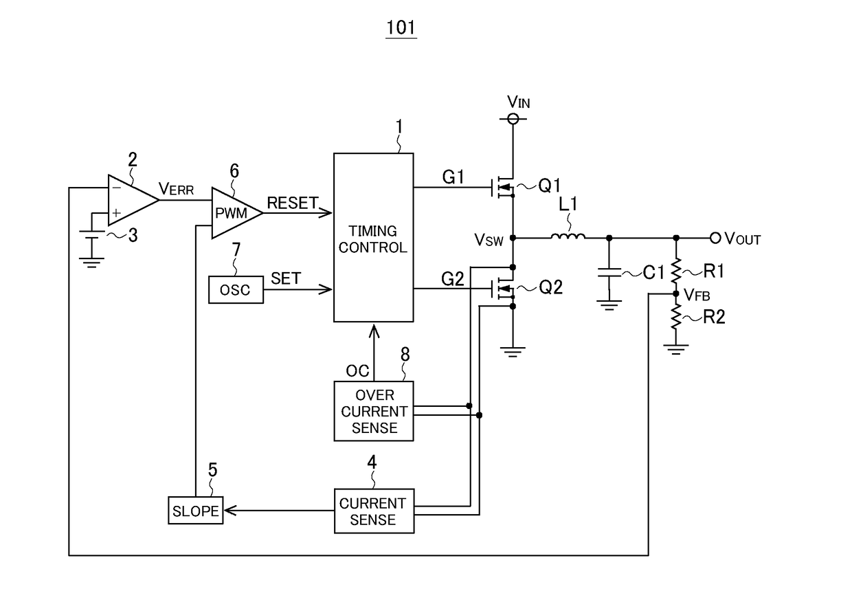
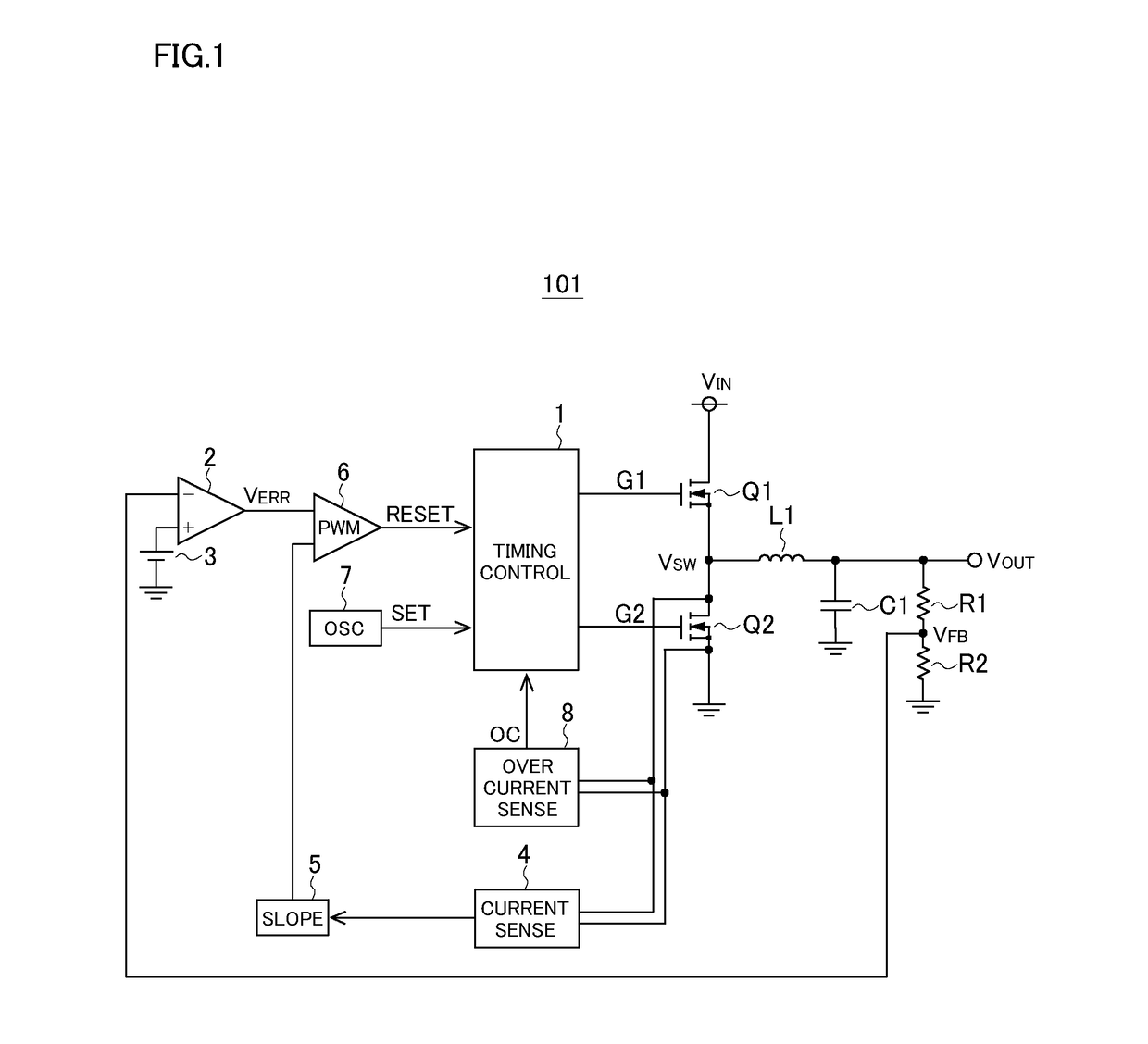
[0035]Overall Configuration: FIG. 1 is a diagram showing an example of the overall configuration of a current-mode-control switching power supply device (current-mode-control switching regulator). The switching power supply device 101 of this configuration example is a current-mode-control switching power supply device that performs step-down operation to step down an input voltage, and includes a timing control circuit 1, a high-side MOS transistor Q1, a low-side MOS transistor Q2, an inductor L1, an output capacitor C1, voltage division resistors R1 and R2, an error amplifier 2, a reference voltage source 3, a current sense circuit 4, a slope circuit 5, a comparator 6, an oscillator 7, and an overcurrent sense circuit 8.

[0036]The timing control circuit 1 controls the ON / OFF states of the high-side and low-side MOS transistors Q1 and Q2, and generates gate signals G1 and G2 for the high-side and low-side MOS transistors Q1 and Q2 respectively according to a set signal SET and a res...


PUM


Abstract

A switching regulator control circuit is used in a switching regulator that converts an input voltage into an output voltage by the switching of a switching device, and generates a switching signal for controlling the ON/OFF operation of the switching device. The switching regulator control circuit has a fault detector and a fault protector. The fault detector detects, based on the duty ratio of the switching signal or a variable correlated to it and included in a control signal used to generate the switching signal, a fault state where the duty ratio falls outside the normal modulation range. The fault protector stops the switching of the switching device when the fault detector detects a fault state.

Description

[0001]This nonprovisional application claims priority under 35 U.S.C. §119(a) on Patent Application No. 2015-256555 filed in Japan on Dec. 28, 2015 and Patent Application No. 2016-162121 filed in Japan on Aug. 22, 2016, the entire contents of which are hereby incorporated by reference.BACKGROUND OF THE INVENTION[0002]1. Field of the Invention[0003]The present invention relates to switching regulators.[0004]2. Description of Related Art[0005]Methods for controlling switching power supply devices (switching regulators) that stabilize the output voltage by varying the duty ratio of the switching signal according to extraneous disturbances such as variation of the input voltage and variation of the output current divide roughly into those relying on voltage mode control and those relying on current mode control. In general, methods relying on current mode control are highly effective in terms of simple phase compensation, fast response, and reduced numbers of externally fitted component...

Claims


Application Information

Patent Timeline
Patent Type & Authority Applications(United States)
IPC IPC(8): H02M1/088H02H7/12B60R16/033H03K17/082H02M3/158
CPCH02M1/088H03K17/082H02M2001/0009B60R16/033H02H7/1213H02M3/158H02M1/32H02M1/0025H02M1/0009
Inventor YAMAGUCHI, YUHEITATEISHI, TETSUO
Owner ROHM CO LTD
Why Eureka
Try Eureka