Method for controlling an electric motor of a power tool

Active Publication Date: 2017-07-06
ROBERT BOSCH GMBH
View PDF26 Cites 18 Cited by
  • Summary
  • Abstract
  • Description
  • Claims
  • Application Information

AI Technical Summary

Benefits of technology

[0004]An advantage of the example method according to the present invention described herein is that at least a current of the electric motor and/or a rotation speed of the electric motor during an impact operating mode of the electric motor is detected as a parameter, and a dr

Problems solved by technology

The excessively low torque

Method used


Image

  • Method for controlling an electric motor of a power tool
  • Method for controlling an electric motor of a power tool
  • Method for controlling an electric motor of a power tool

Examples


Embodiment Construction

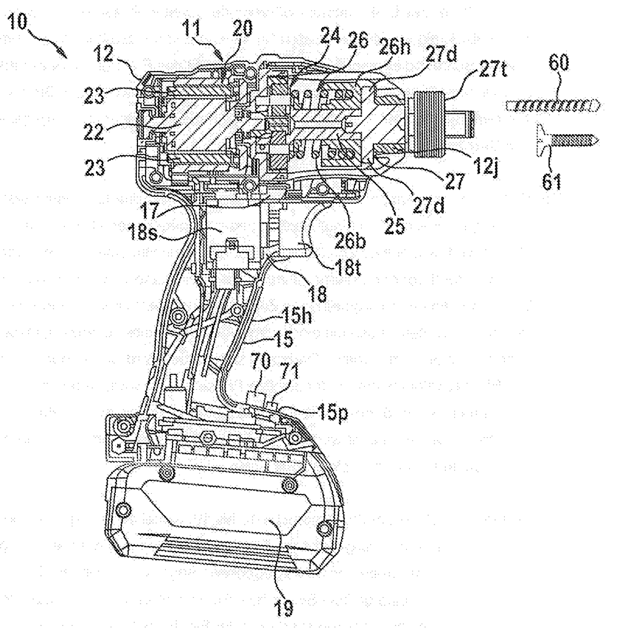
[0036]FIG. 1 schematically depicts a power tool 10 that is embodied in the form of an impact driver 10. Impact driver 10 has a housing 11 that has a cylindrical main body 12 and a handle 15 attached thereto. A battery 19 is disposed oppositely to main body 12. Disposed in main body 12 is an electric motor 20 in the form of a brushless DC motor 20 having a planetary gearbox 24, a spindle 25, an impact generating mechanism 26, and an anvil 27. Electric motor 20 serves as a drive source for the rotating impact generating mechanism 26. The rotation speed of electric motor 20 is reduced with the aid of planetary gearbox 24 and then transferred to spindle 25. The rotational force of spindle 25 is converted into a rotating impact force by impact generating mechanism 26, a hammer 26h and a compression spring 26b being provided for that purpose. An impact force of hammer 26h is transferred to anvil 27. Anvil 27 is mounted rotatably around an axis and is driven by the rotational impact force ...


PUM


Abstract

A method for controlling an electric motor of a power tool having a receptacle for a tool, at least a current of the electric motor and/or a rotation speed of the electric motor during an impact operating mode of the electric motor being detected as a parameter, a driving time of the electric motor for the impact operating mode being specified as a function of the detected parameter. A method is also described for controlling an electric motor of a power tool having a receptacle for a tool for unscrewing a screw from a mating part.

Description

FIELD[0001]The present invention relates to a method for controlling an electric motor of a power tool, and to a control device.BACKGROUND INFORMATION[0002]Conventionally, an electric motor of a power tool is controlled as a function of an actuation of a switch. In this context, control is applied to the electric motor, for example, with a predefined rotation speed or with a predefined torque.[0003]An object of the invention is to furnish an improved method for controlling the electric motor, an improved control device, and an improved power tool.SUMMARY[0004]An advantage of the example method according to the present invention described herein is that at least a current of the electric motor and / or a rotation speed of the electric motor during an impact operating mode of the electric motor is detected as a parameter, and a driving time of the electric motor for the impact operating mode is specified as a function of the detected parameter. Improved control application to the electr...

Claims


Application Information

Patent Timeline
IPC IPC(8): B25B23/147B25B23/00
CPCB25B23/0064B25B23/1475B25F5/00H02P6/28H02P2205/05
Inventor LEONG, CHI HOETAN, JU-LIENTAN, KAH HOOISTIEFEL, MORITZYEOH, SIM TEIK
Owner ROBERT BOSCH GMBH
Why Eureka
Try Eureka