Self-tensioning modular panels

a self-tensioning, modular technology, applied in the direction of heat-proofing, solar heating energy, heat collector mounting/support, etc., can solve the problems of product that is not as efficient or easy to install or handle, sagging or drooping of shade material normally, etc., to reduce evaporation loss and reduce energy loss on the roof.

Inactive Publication Date: 2017-07-06
FORBIS JACK R +1
View PDF57 Cites 3 Cited by
  • Summary
  • Abstract
  • Description
  • Claims
  • Application Information

AI Technical Summary

Benefits of technology

[0016]In another aspect, there is provided a method of reducing evaporation losses from a body of water comprising the steps of: (a) forming one or more modular shading panels, each of which comprising a closed-loop frame and a covering wherein (i) the covering comprises a first layer, a second layer, a closed peripheral portion where the first layer and the second layer are joined, and an open peripheral portion and (ii) the closed-loop frame is fully received in the covering through the open peripheral portion and the open peripheral portion is closed to form the modular shading panel wherein the closed-loop frame is fully contained in and concealed by the covering, the first layer of the covering forms a first side of the modular shading panel, the second layer of the covering forms an opposing second side of the modular shading panel, and the first side of the modular shading panel is spaced apart from the second side of the modular shading panel; and (b) placing the one or more modular shading panels in a floating or a fixed position on or above a surface of the body of water. By way of example, but not by way of limitatio

Problems solved by technology

When constructing shade structures of many types, various challenges arise such as attempting to handle large sheets or sections of shade materials, especially in windy conditions.
If shade structures are envisioned and built that do not utilize a “tensioned fab

Method used


Image

  • Self-tensioning modular panels
  • Self-tensioning modular panels
  • Self-tensioning modular panels

Examples


Embodiment Construction

[0034]The devices and methods discussed herein are merely illustrative of specific manners in which to make and use this invention and are not to be interpreted as limiting in scope.

[0035]While the devices and methods have been described with a certain degree of particularity, it is to be noted that many modifications may be made in the details of the construction and the arrangement of the devices and components without departing from the spirit and scope of this disclosure. It is understood that the devices and methods are not limited to the embodiments set forth herein for purposes of exemplification.

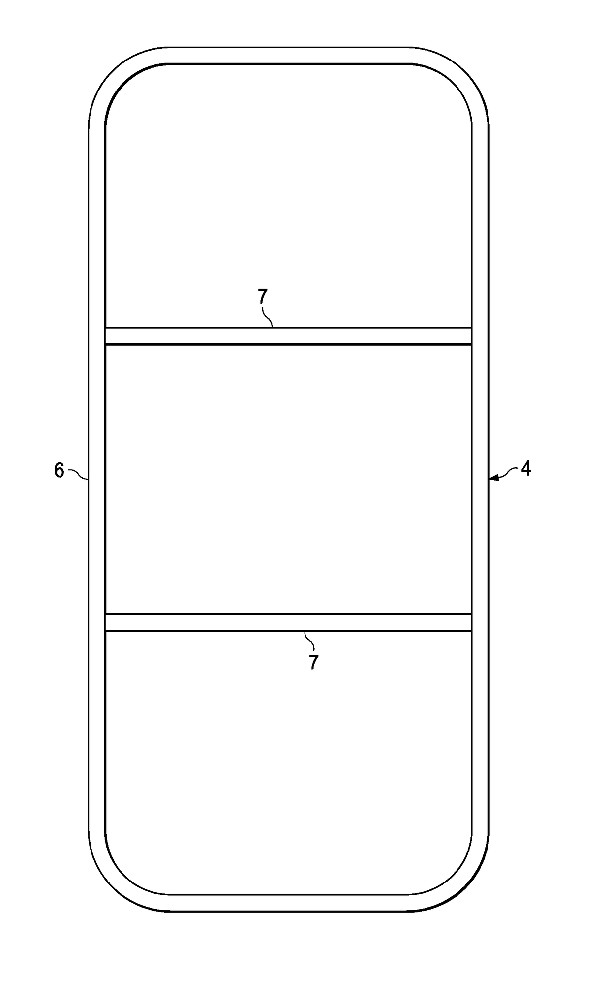
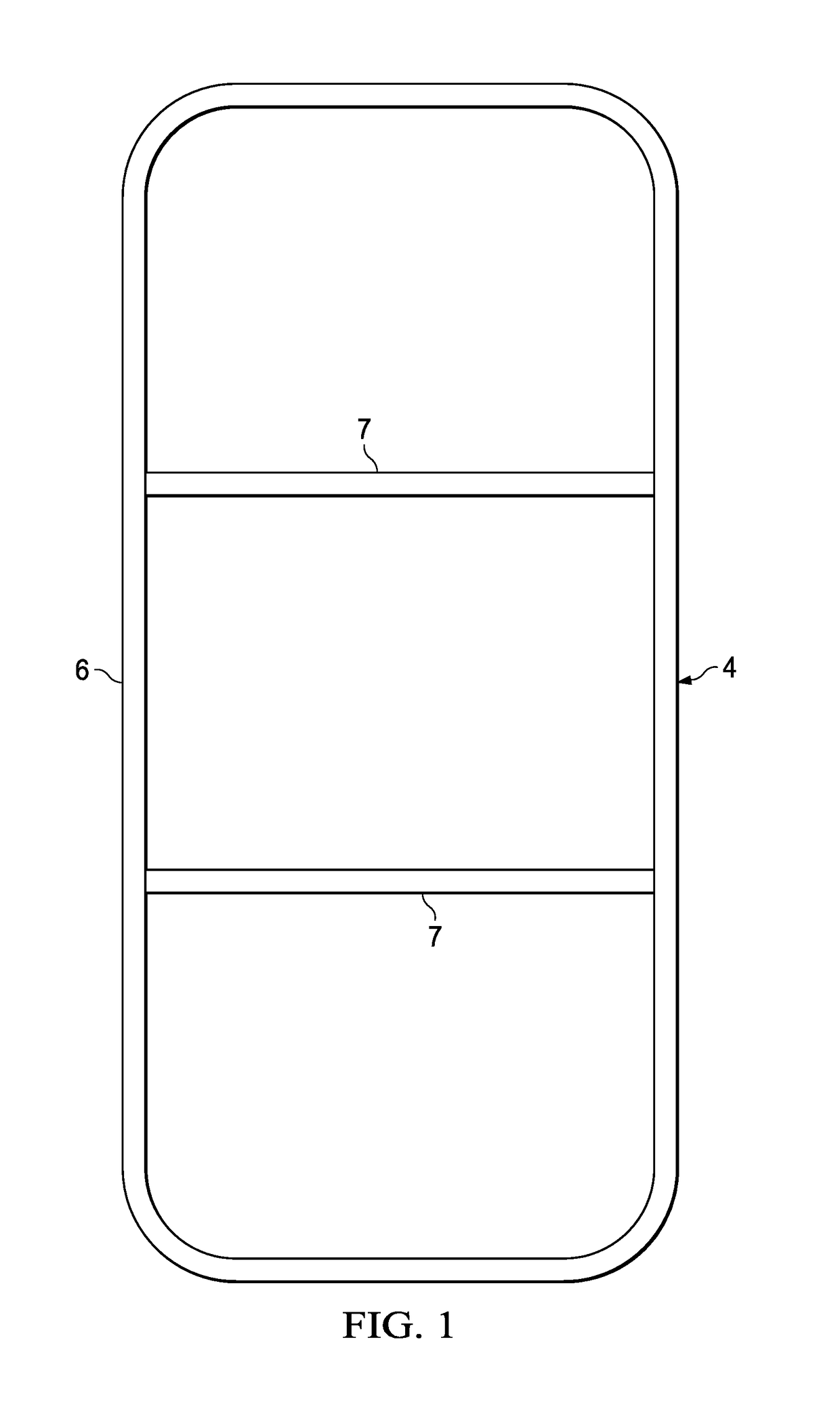
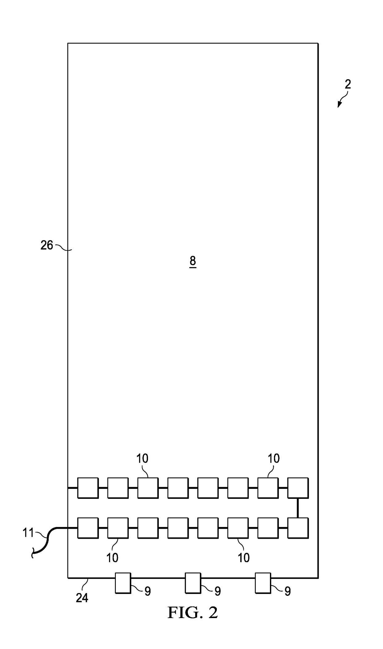
[0036]In general, in a first aspect, the invention relates to a new, unique, lightweight, modular panel 2 that has excellent insulating characteristics and has many uses / applications. It consists of a sufficiently rigid framework 4 (which is very different from traditional shade structure frameworks and which, in most applications, may be rectangular in shape but also may be square, ...


PUM


Abstract

An innovative, low-density, highly-insulating modular panel for use in many applications and industries. The panel has a frame that may be preformed or bent and may be made of rigid or flexible material, and a panel covering comprising at least one pocket of thin, low-density shade fabric that has the capability of sufficiently stretching to surround the frame when the pocket is pulled onto it. The pocket may be then secured, along any previously open end where the frame was inserted, by various fastening devices. The panel covering pocket may have additional features added, as described herein. The panel is durable and cost-effective, and has good solar-control and insulating qualities. It is also a windbreak panel, a noise-reduction panel, an impact protection panel, a water-resistant panel, a fall protection panel, and a pollution-control panel. Two or more panels can be joined to create a structure-protecting panel assembly or system.

Description

RELATED CASES[0001]This application is a continuation-in-part application of co-pending U.S. patent application Ser. No. 14 / 465,080 filed Aug. 21, 2014, which was a divisional of U.S. patent application Ser. No. 13 / 118,791 filed May 31, 2011, which was a continuation of U.S. patent application Ser. No. 12 / 011,595 filed Jan. 28, 2008.FIELD OF THE INVENTION[0002]The present invention relates to a unique, modular panel that has significant insulating and protective characteristics along with many uses / applications in various industries. The modular panel of the present invention serves as a new type of “shade panel” (which alone, or in combination with other like or identical panels, creates a new type of “shade structure” or “shading device”). Additionally, the panel of the present invention can be utilized as an improved type of windbreak panel, a privacy panel, and as a greatly improved impact protection panel. The innovative panels of the present invention represent a significant i...

Claims


Application Information

Patent Timeline
IPC IPC(8): E04B2/74E04B1/92E04C2/38E06B9/24H02S20/23E04F10/00E04D13/00E04D13/04H02S30/10E04B1/80A47G5/00
CPCE04B2/7422E04B1/80E04B1/92E04C2/38E06B9/24E04B2002/7479E04F10/00E04D13/00E04D13/0404H02S30/10H02S20/23A47G5/00Y02E10/50E04C2/384H01L31/042H02S20/22E04F10/08E06B7/08E06B9/00E04F10/005E06B2009/005B60J1/2094E04B2/7407F24S2025/6001F24S25/60E04H9/027E04G23/0218Y02B10/10Y02P80/20
Inventor FORBIS, JACK R.FORBIS, ANN R.
Owner FORBIS JACK R
Why Eureka
Try Eureka