Ultra hush exhaust system (UHES)

a technology of exhaust system and ultra-hush, which is applied in the field of ultra-hush system, can solve the problems of large financial loss to the owner, undesirable noise at the airport, and noise pollution at the airport, and achieve the effect of reducing the noise of the jet engine and minimal loss of thrus

Active Publication Date: 2017-07-06
OSMAN MEDHAT
View PDF23 Cites 12 Cited by
  • Summary
  • Abstract
  • Description
  • Claims
  • Application Information

AI Technical Summary

Benefits of technology

[0012]It is a primary object of this invention to provide a method of reducing jet engine noise at all frequencies with minimal loss of thrust, and possibly some gain in thrust, by employing an ejector assembly having a mixing zone into which a secondary air stream is injected at a relatively higher static pressure.
[0016]The clamshell doors are either semi-circular or square / rectangular / trapezoidal shape similar in concept to the aforementioned ULTRA REVERSER U.S. Pat. Nos. 5,615.834 and / or 7,043,897. The clamshell doors consist of an inner and outer skins mechanically connected at the edges. Two major innovative improvements are made to the doors. The First improvement to the design of the clamshell doors where the inner skin is fitted with guide vanes to direct the cool eductor air towards the middle of the door to blanket the inner skin with the cool air and to mix this cool air with the hot gases from the engine exhaust to reduce the overall gas temperature to enable the use of lower temperature material in the design of the clamshell doors. The Second improvement to the inner skin is by making a slot upstream of the inner skin to allow the reversed flow flowing along the door in the reverse thrust deploy mode to split into two flow components, one flowing towards the kicker plate then forward to produce the desired reverse thrust, while the second component of the split flow of the reversed flow flows between the inner and outer skin exiting through slots in the kicker plate of the inner skin, forward producing a forward component pushing the first flow component downward and forward instead of flowing upward, thereby maximizing reverse thrust efficiency.

Problems solved by technology

This high acoustic signature results in noise pollution at airports and undesirable noise during Approach, Take-Off or flying at low altitude over residential areas located near the approach path of airports.
This in turn will extend the service life of this type of aircrafts instead of having to replace their engines with new quieter engines or disposing of the aircraft all together since it violates the noise regulations, which constitutes a major financial loss to the owner.

Method used


Image

  • Ultra hush exhaust system (UHES)
  • Ultra hush exhaust system (UHES)
  • Ultra hush exhaust system (UHES)

Examples


Embodiment Construction

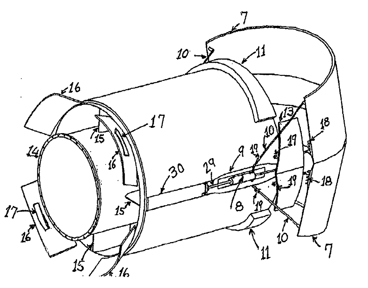
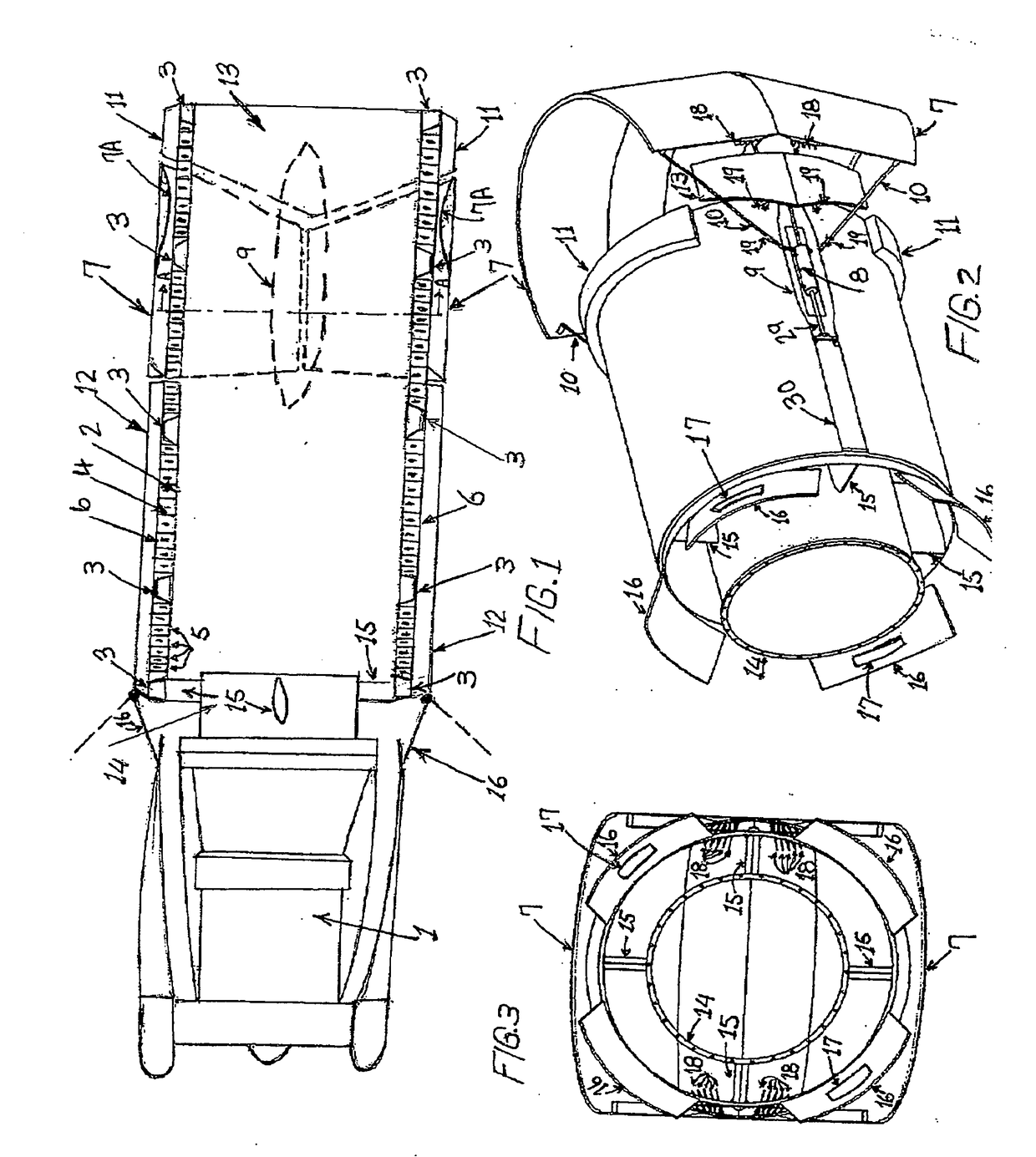
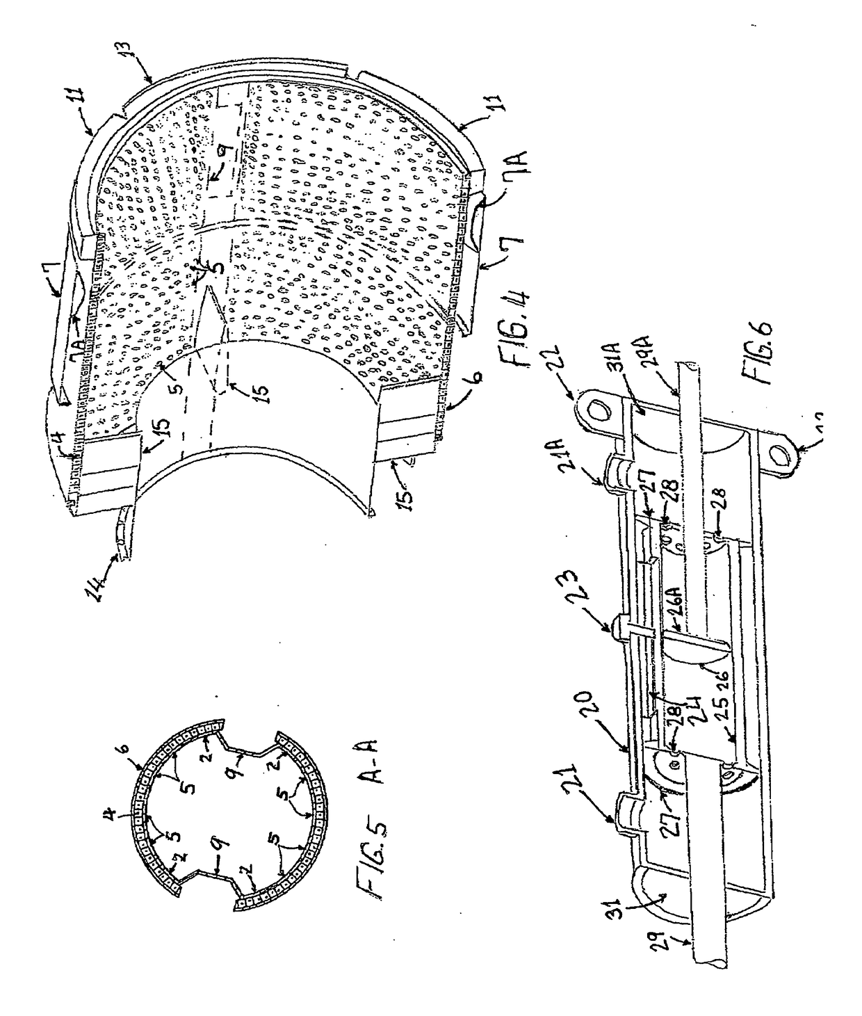
[0025]The design concept included in preferred embodiments in FIG. 1 is for a sound attenuation system referred to as the UHES which is mounted to the rearmost aft turbine frame of a Jet Engine 1. The UHES consists of an integrally constructed double walled duct illustrated in FIG. 1 with a constant cross-section area or can be a convergent duct as shown in FIG. 10. The UHES duct consists of an inner skin 2 integrally constructed with circular corrugations 3, referred to also as ribs or hats or ridges, which act as supporting frames, with the areas in between those frames in the inner skin are perforated where sound attenuation material 4, which can be honeycomb or any other appropriate material are located on top of the perforations 5. The outer skin 6 is continuous with no perforations, and is appropriately fastened or welded to the ribs 3 of the inner skin 2.

[0026]At the rear end of the integrally constructed double walled duct, two semi-circular or square shaped clamshell doors ...


PUM


Abstract

An exhaust noise attenuation system mounted to a Jet Engine exit turbine frame for noise attenuation with an ULTRA THRUST REVERSER System mounted at the exhaust end, aft end of the exhaust noise attenuation system, to provide deceleration after landing of the aircraft. The exhaust noise attenuation system consists of double walled duct which can be either of constant circular, square or elliptic cross section or convergent section with variable cross-section area, made of sheet metal double walls with a perforated inner wall or skin except in the areas where there are solid non-perforated corrugations or hat sections which act as frames for structural integrity of the double walled duct, and a non-perforated outer wall or skin, with an appropriate noise attenuation material, assuming honeycomb for the sake of discussion since it is widely used, sandwiched between the inner perforated and outer solid skins of the duct. The sound attenuation material is placed in between the corrugations / hat sections over the perforations of the inner skin. The double walled duct is connected to a nozzle / ring bolted to the engine frame using two or more struts. In the shown figures the inventor used four (4) struts for depiction. Hinged inlet Doors are mounted at the forward end of the double skin duct, controlled by the pilot or the engine control system, to control the flow of ambient air sucked into the exhaust system by the eductor action, to optimize the engine performance, noise signature and reduce ram drag during flight. The doors can also be closed tight during flight to reduce ram drag and to create a smooth surface for the ambient air flowing over the surface of the exhaust system. However, the doors can be fitted with smaller doors or scoops to provide a limited amount of airflow to cool off the walls of the inner perforated duct. A movable exit cone can be used with the convergent duct configuration to optimize the exit area of the double walled duct to optimize the engine performance. An ULTRA THRUST REVERSER SYSTEM is mounted at the aft end of the double walled duct, consists of two improved design clamshell doors mounted on either side of the top and bottom of the double walled duct, fitted with two unique design actuators mounted one on each side of the external sides of the duct between the clamshell doors and the duct, possibly in a depression in the duct called blister, assuming them to be hydraulic actuators for discussion purposes. The actuators drive the clamshell doors using linkages pivoted to the exterior of the double walled duct, connecting the doors to the actuators, to deploy the doors aft of the double walled duct during deceleration after landing, diverting the exhaust gases forward to slow down the aircraft, but also drive the two movable fairings during thrust reverser operation to enclose the reversed exhaust flow forward to prevent its impingement on the skin of the aircraft.

Description

FIELD OF INVENTION[0001]This invention relates to what is known in the Aviation Industry as a hush system aiming at reducing the noise signature of older types of jet engines known as Turbojets or Low Bypass Jet Engines.[0002]This patent relates to the Application Document No. 61 / 626,873 Filed on Oct. 5, 2011.BACKGROUND OF THE INVENTION[0003]An ejector / eductor (those two words are used interchangeably) arrangement using a double walled duct mounted to the aft engine frame and method of reducing jet engine noise are disclosed wherein the primary combustion gas stream of the jet engine is ejected into a mixing section or zone of the double walled duct, into which a secondary external cool gas stream from ambient air is injected at a velocity sufficient to create a mixed flow condition, resulting in rapid mixing of the primary and secondary gas streams both in the mixing zone. The ejector, in the convergent configuration, can be provided with means for adjusting the exit area of the mi...

Claims


Application Information

Patent Timeline
Patent Type & Authority Applications(United States)
IPC IPC(8): F02K1/82F02K1/60
CPCF02K1/82F02K1/60F05D2240/128F05D2250/283F05D2220/323F02K1/36F02K1/383F02K1/827F02K1/34
Inventor OSMAN, MEDHAT
Owner OSMAN MEDHAT
Why Eureka
Try Eureka