
Solid state photomultiplier with wide temperature range of operation

a photomultiplier and solid state technology, applied in the field of detection systems, can solve the problems of increasing the cost of the device, limiting the typical sspm, and uncertainty in the magnitude of the actual underlying event being measured, and achieve the effect of constan

Active Publication Date: 2017-07-06
MANTHEY DIANE MANT
View PDF4 Cites 6 Cited by
  • Summary
  • Abstract
  • Description
  • Claims
  • Application Information

AI Technical Summary

Benefits of technology

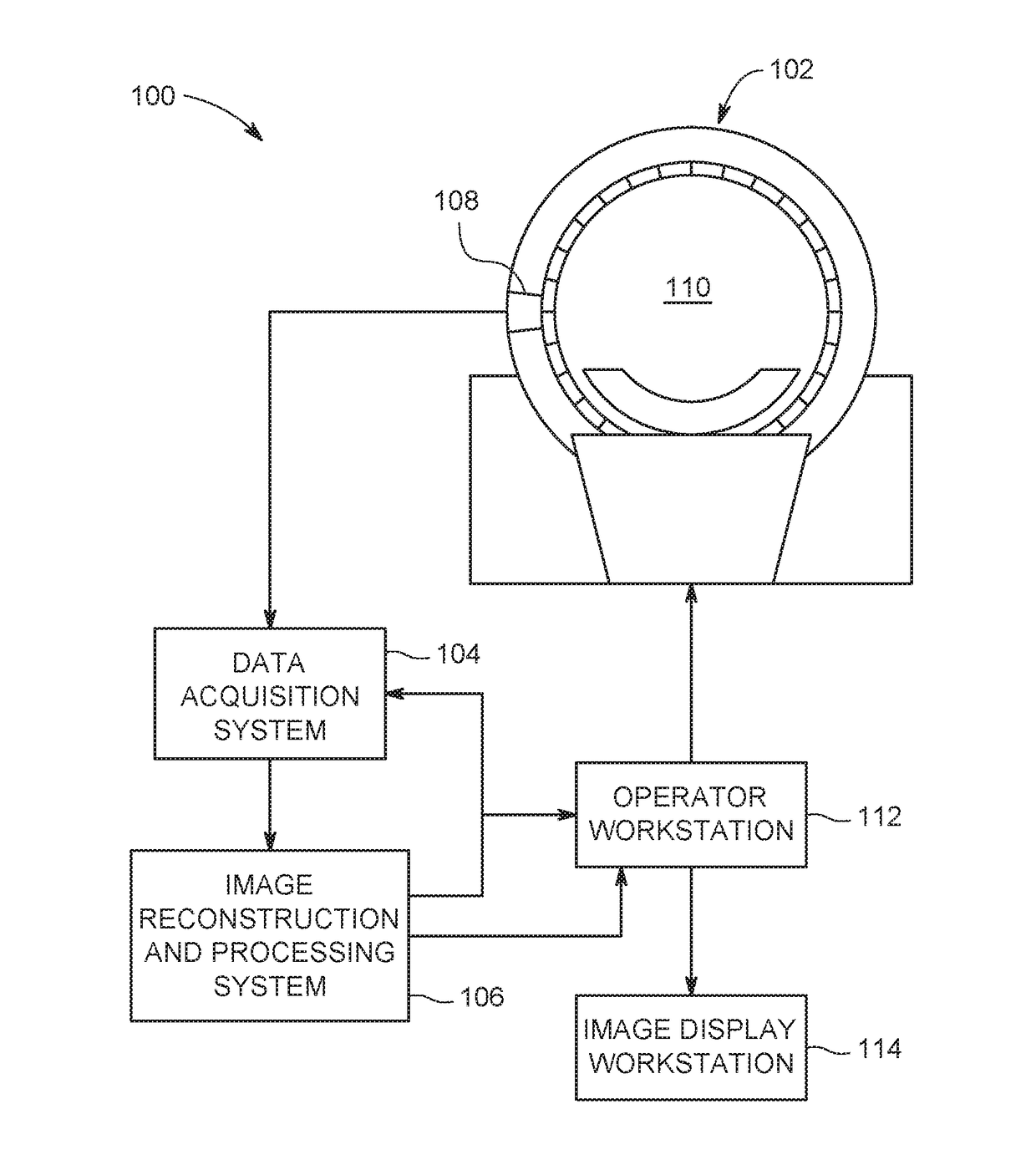
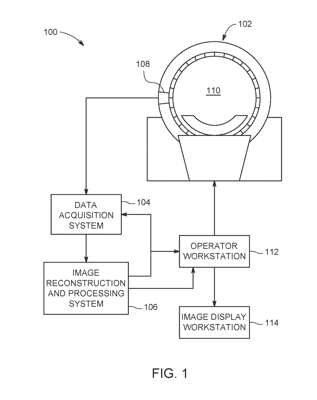
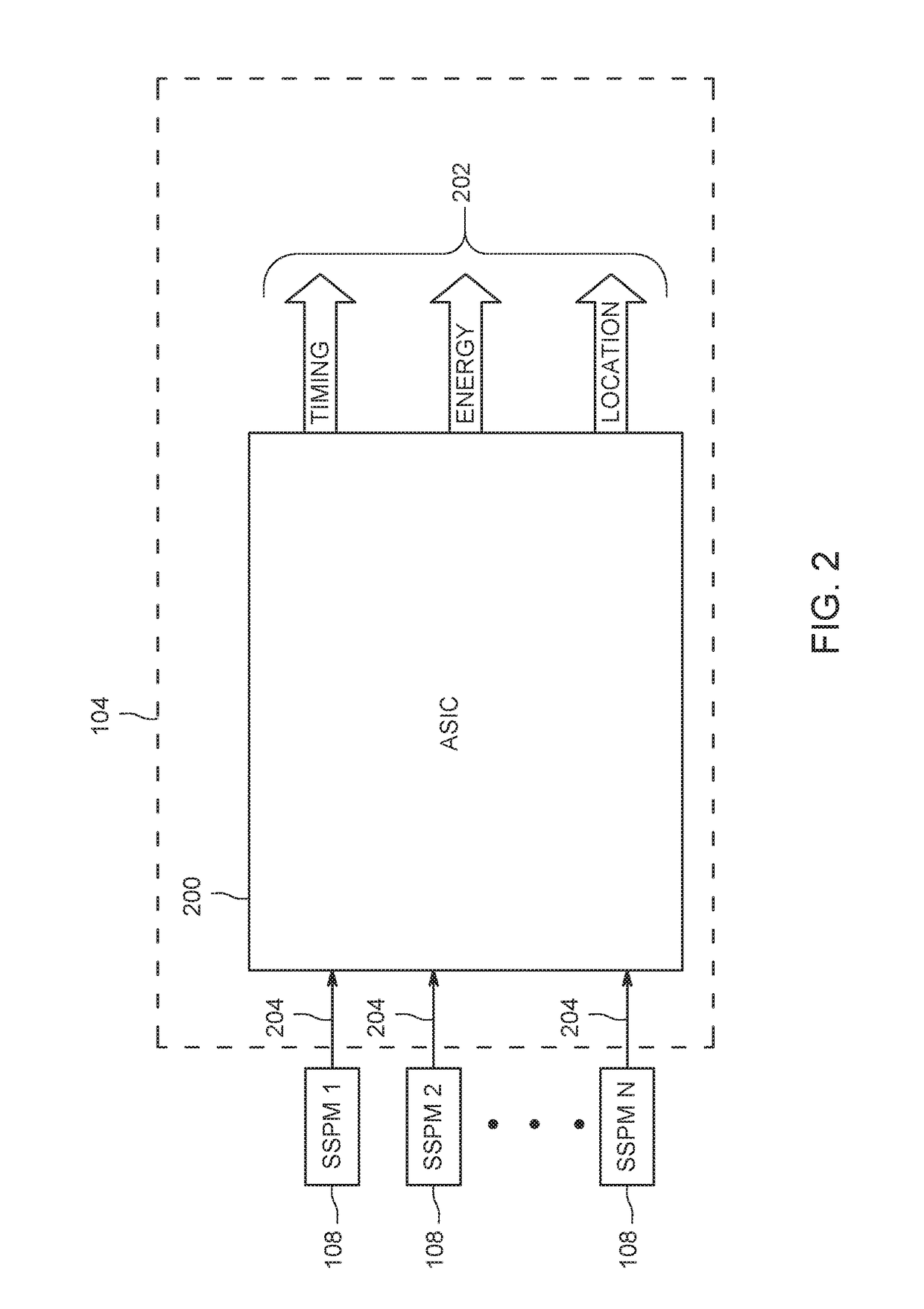
The patent text describes a new type of photomultiplier that detects light and converts it into an electrical signal. This detector is made up of an array of small cells, each containing a photodiode and a quench circuit. These cells are designed to have a constant temperature resistance over a range of temperatures. By measuring the signals generated by these cells, the detector can capture images with high accuracy and frame rates. The patent also includes a detection module that can be used in a radiation detection system. The imaging system can generate high-quality images and has applications in various fields such as medical imaging and security.

Problems solved by technology

Thus, variations in gain due to temperature effects may lead to uncertainty with respect to the magnitude of the actual underlying event being measured.
All of these solutions require additional hardware, which can increase the cost of the device.
Additionally, even with this additional hardware, the typical SSPM is limited to moderate temperature environments, e.g., a hospital room with a PET scanner, where the SSPM can be easily cooled and / or regulated.
The temperature dependence of an SSPM has made it difficult to utilize SSPMs in applications where a wide range of operational temperatures are experienced, such as with the gamma rays and neutron radiation detected in oil exploration drilling, for example, or the measurement of the flame from a gas turbine engine, which typically exhibit significantly harsher thermal environments.

Method used


Image

  • Solid state photomultiplier with wide temperature range of operation
  • Solid state photomultiplier with wide temperature range of operation
  • Solid state photomultiplier with wide temperature range of operation

Examples


Embodiment Construction

[0016]In the following specification and the claims, reference will be made to a number of terms, which shall be defined to have the following meanings.

[0017]The singular forms “a”, “an”, and “the” include plural references unless the context clearly dictates otherwise.

[0018]“Optional” or “optionally” means that the subsequently described event or circumstance may or may not occur, and that the description includes instances where the event occurs and instances where it does not.

[0019]Approximating language, as used herein throughout the specification and claims, may be applied to modify any quantitative representation that could permissibly vary without resulting in a change in the basic function to which it is related. Accordingly, a value modified by a term or terms, such as “about”, “approximately”, and “substantially”, are not to be limited to the precise value specified. In at least some instances, the approximating language may correspond to the precision of an instrument for...


PUM


Abstract

A solid state photomultiplier includes at least one microcell configured to generate an initial analog signal when exposed to optical photons. The solid state photomultiplier further includes a quench circuit electrically coupled with the at least one microcell. The quench circuit includes at least one quench resistor configured to exhibit a substantially constant temperature coefficient of resistance over a selected temperature range.

Description

BACKGROUND[0001]The field of this disclosure relates generally to detection systems for use in imaging systems, and more specifically, to solid-state photomultipliers having a wide temperature range of operation in a detection system.[0002]Many known imaging detector systems use a solid-state photomultiplier (SSPM) in combination with a scintillator. The scintillator converts x-rays and gamma rays to visible light photons whereupon a photodiode of the SSPM converts these photons to photocurrent. SSPMs have come to replace photomultiplier tubes (PMTs) in the field due to the SSPM's lower manufacturing costs, lower power requirements, compact size, mechanical durability, insensitivity to magnetic fields, and uniformity of response. SSPMs have become widely used as detection elements for computed tomography (CT), single photon emission computed tomography (SPECT), and positron emission tomography (PET) machines and applications. SSPMs have also become known for gamma ray detection in o...

Claims


Application Information

Patent Timeline
IPC IPC(8): G01T1/24H01L31/115
CPCG01T1/248H01L31/115G01T1/249G01T1/208H01L31/02027H01L27/14663H01L31/107G01T1/20182
Inventor SANDVIK, PETER MICAHSOLOVIEV, STANISLAV IVANOVICHDOLINSKY, SERGEI IVANOVICHMCMAHON, JAMES JAYPALIT, SABARNI
Owner MANTHEY DIANE MANT
Learn More