Small form factor flame resistant low smoke halogen free fiber optic cable

a fiber optic cable, flame-resistant technology, applied in the direction of bundled fibre light guides, instruments, fibre mechanical structures, etc., can solve the problems of reducing the rated tension, and increasing the optical loss along the length of the optical fiber, so as to avoid high optical attenuation and optical loss, the effect of minimizing the shrinkage of the exterior jack

Active Publication Date: 2017-07-06
PROTERIAL CABLE AMERICA INC
View PDF0 Cites 9 Cited by
  • Summary
  • Abstract
  • Description
  • Claims
  • Application Information

AI Technical Summary

Benefits of technology

[0019]Another object of the present invention is to minimize shrinkage of the exterior jacket so as to avoid high optical attenuation and optical losses in the fiber optic cable.

Problems solved by technology

This pressure is not uniform and typically leads to micro and macro bending of the internal optical fiber which, in turn, leads to a significant increase in optical losses along the length of the optical fiber.
This also leads to design and performance compromises, such as lower rated tensions, the need for additional strength members, or a reduction in the temperature range of operation of the cable.
However, the inclusion of strength members in the jacket or outer tube of the cable construction generally leads to an undesirable increase in cable diameter.
Another disadvantage of the strength members located in the jacket or outer tube is a preferential bending direction, due to the asymmetric rigidity caused by the localized presence of the strength members.
A key problem with using yarns as tensile strength members is that they have very little compression modulus, but very high tensile modulus.
This lack of compression strength typically requires other techniques for controlling the amount the cable shrinks over time, or due to temperature changes.
Other materials were not considered because they had low hardness or flex modulus values, which could negatively affect impact and compression performance of the jacket.
Of the remaining materials, a group of compounds were selected for cable trials and of these tested compounds, many failed due to problems such as either the inability to be able to form a thin wall jacket or failed due to extrusion inconsistencies, e.g., the extruded material has holes, tears or other imperfections in the jacket.
Material shrink back is also another obstacle that can lead to unsuccessful cable performance results, and it was determined that a low amount of shrink back is important in order to maintain the desired cable performance.
However, certain post extrusion conditions, such as temperature cycling of the cable across its storage and operating temperature range, cause these stresses to relax, which results in a longitudinal shrinking of the jacket.
This shrinkage will increase the EFL beyond a critical point and can result in high optical losses in the cable.

Method used


Image

  • Small form factor flame resistant low smoke halogen free fiber optic cable
  • Small form factor flame resistant low smoke halogen free fiber optic cable
  • Small form factor flame resistant low smoke halogen free fiber optic cable

Examples


first embodiment

[0070]Turning now to FIG. 11, a detail description concerning the various components of a first embodiment or subassembly will now be discussed. As can be seen in this embodiment, the fiber optic cable 2 generally comprises an exterior first jacket 4 which surrounds and encases a variety of different internal components, each of which will be discussed below in further detail. The first jacket 4 is typically manufactured from a plastic material, such as blended polyolefins that contain flame retardant material which result in a relatively high limiting oxygen index, e.g., a LOI of at least 40 (preferably 50), that renders the exterior first jacket 4 resistant to being ignited when exposed to heat or an open flame. A suitable blended polyolefins material, for use in manufacture of the first jacket 4 (single assembly cable), is a proprietary formulation sold by Teknor Apex of 505 Central Avenue, Pawtucket, R.I. 02861 under the Halguard 58350 trade name. Another desired characteristic ...

second embodiment

[0087]Turning now to FIG. 13, a detailed description concerning the disclosure will now be provided. As this embodiment is similar to the previous embodiment in many respects, identical elements will be given identical reference numerals.

[0088]According to this embodiment, first and second subassemblies 14, 16, each of which is generally formed as described above with respect to the description relating to FIG. 11, are first assembled generally independently of one another. As shown, the first subassembly 14 includes a first jacket 4 that surrounds and encases 12 optical fibers 6 while the second subassembly 16 also includes a first jacket 4 that surrounds and encases an additional 12 optical fibers 6. The first jacket 4, of each one of the first and the second subassemblies 14, 16, also surrounds and encases a plurality of reinforcing strands 8 which are arranged so as to separate and space apart each one of the individual optical fibers 6 from any adjacent optical fiber(s) 6 conta...

third embodiment

[0095]Turning now to FIG. 14, a detailed description concerning the disclosure will now be provided. As this embodiment is similar to the previous embodiments in many respects, identical elements will be given identical reference numerals.

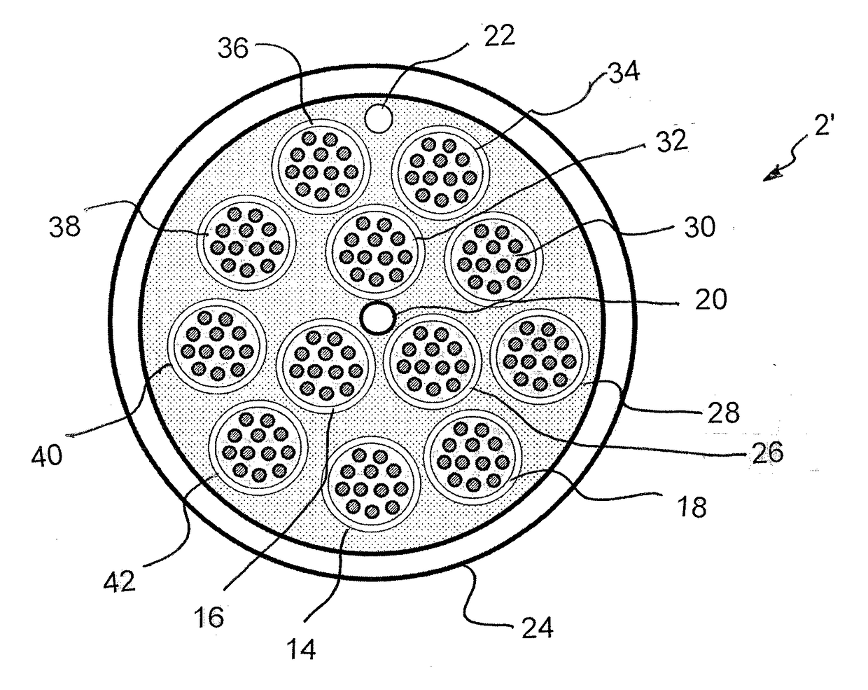
[0096]According to this embodiment, first, second, third and fourth subassemblies 14, 16, 18, 26 each of which is generally formed as described above with respect to FIG. 11, are first assembled generally independently of one another. As shown, the first subassembly 14 includes a first jacket 4 that surrounds and encases 12 optical fibers 6, the second sub 16 unit includes a first jacket 4 that surrounds and encases 12 optical fibers 6, the third subassembly 18 includes a first jacket 4 that surrounds and encases 12 optical fibers 6 while the fourth subassembly 26 also includes a first jacket 4 that surrounds and encases an additional 12 optical fibers 6. The first jacket 4, of each one of the first, the second, the third and the fourth subassembli...


PUM


Abstract

A fiber optic cable which comprises at least one subassembly. Each subassembly comprises 1 to 12 optical fibers, a plurality of yarn strength members free halogens, and a first jacket free of any halogens and having a thickness of between about 0.254 to about 0.305 mm. The first jacket surrounds and completely encases the 1 to 12 optical fibers and the plurality of yarn strength members to form the subassembly. The first jacket is manufactured from a material which has a limiting oxygen index (LOI) of at least 40 and a shrinkage of the first jacket being no greater than about 3.5%. The fiber optic cable has a crush resistance of at least 35 N / cm, allows less than a 0.4 db / km increase of optical attenuation from −20 to 70 C and meets requirements according to each of IEC 60332-3-24 (Flame Spread), IEC 61034-2 (Low smoke), and IEC 60754-1&2 (non-Halogen); and the fiber optic cable has a flexural modulus of about 40,000 psi.

Description

FIELD OF THE INVENTION[0001]The present invention relates to an improved fiber optic cable which contain a plurality of optical fibers and yarn strength members and is completely free of any halogen(s). The fiber optic cable has an exterior jacket material which has a jacket shrinkage of about 3.5% or less, a flex modulus of the outer most tube or jacket is at least about 30,000 psi and preferably 40,000 or more, a limiting oxygen index (LOI) of at least 38 and preferably 50, and meets requirements according to each of IEC 60332-3-24 (Flame Spread), IEC 61034-2 (Low smoke), and IEC 60754-1&2 (non-Halogen).BACKGROUND OF THE INVENTION[0002]As fiber cables continue their growth into premise and the distribution portions of the communication system, a need for smaller cables and higher fiber density grows.[0003]However, smaller cables tend to have a smaller allowable margin of length change compared to larger cables. Smaller cables also have a corresponding smaller amount of space for c...

Claims


Application Information

Patent Timeline
Patent Type & Authority Applications(United States)
IPC IPC(8): G02B6/44G02B6/04
CPCG02B6/04G02B6/4432G02B6/4436
Inventor GONZALEZ, EDUARDO DENIS GARZARICE, HENRICK JASONNARDONE, KENNETH CHRISTOPHERHARDY, JIM
Owner PROTERIAL CABLE AMERICA INC
Why Eureka
Try Eureka