Fluoroscopic Device, Moving Body Tracking Device for Radiation Therapy, and X-Ray Detector

a technology of moving body and tracking device, which is applied in the field of fluoroscopic device, moving body tracking device for radiation therapy, and x-ray detector, can solve the problem that the subject unintentionally moves the body, and achieve the effect of preventing the effect of artifa

Inactive Publication Date: 2017-07-13
SHIMADZU CORP
View PDF0 Cites 19 Cited by
  • Summary
  • Abstract
  • Description
  • Claims
  • Application Information

AI Technical Summary

Benefits of technology

[0026]According to the aspects of the first invention, the seventh invention and the eight invention, the region data of the region other than the correction region is corrected by applying the data from the correction region of the X-ray detector; so that an effect of the artifact due to scattered radiation can be prevented and therefore, the irradiation of the therapeutic beam is not required to be suspended even during performing dynamic body tracking by the X-ray, so that the treatment can be performed expeditiously.
[0027]According to the aspect of the second invention, an effect of the artifact taking place in the orthogonal direction to the gate bus line relative to the X-ray detect

Problems solved by technology

Nevertheless, in some cases, not only the subject unintentionally ma

Method used


Image

  • Fluoroscopic Device, Moving Body Tracking Device for Radiation Therapy, and X-Ray Detector
  • Fluoroscopic Device, Moving Body Tracking Device for Radiation Therapy, and X-Ray Detector
  • Fluoroscopic Device, Moving Body Tracking Device for Radiation Therapy, and X-Ray Detector

Examples


embodiment 1

[0064]FIG. 4 is a schematic view illustrating the state in which a radiation therapy is being performed by a radiation therapeutic apparatus having an X-ray fluoroscopic device according to the aspect of the present invention. In addition, FIG. 5 is a front view illustrating a pair of filters 23 arranged on the surface of the flat panel detector 2.

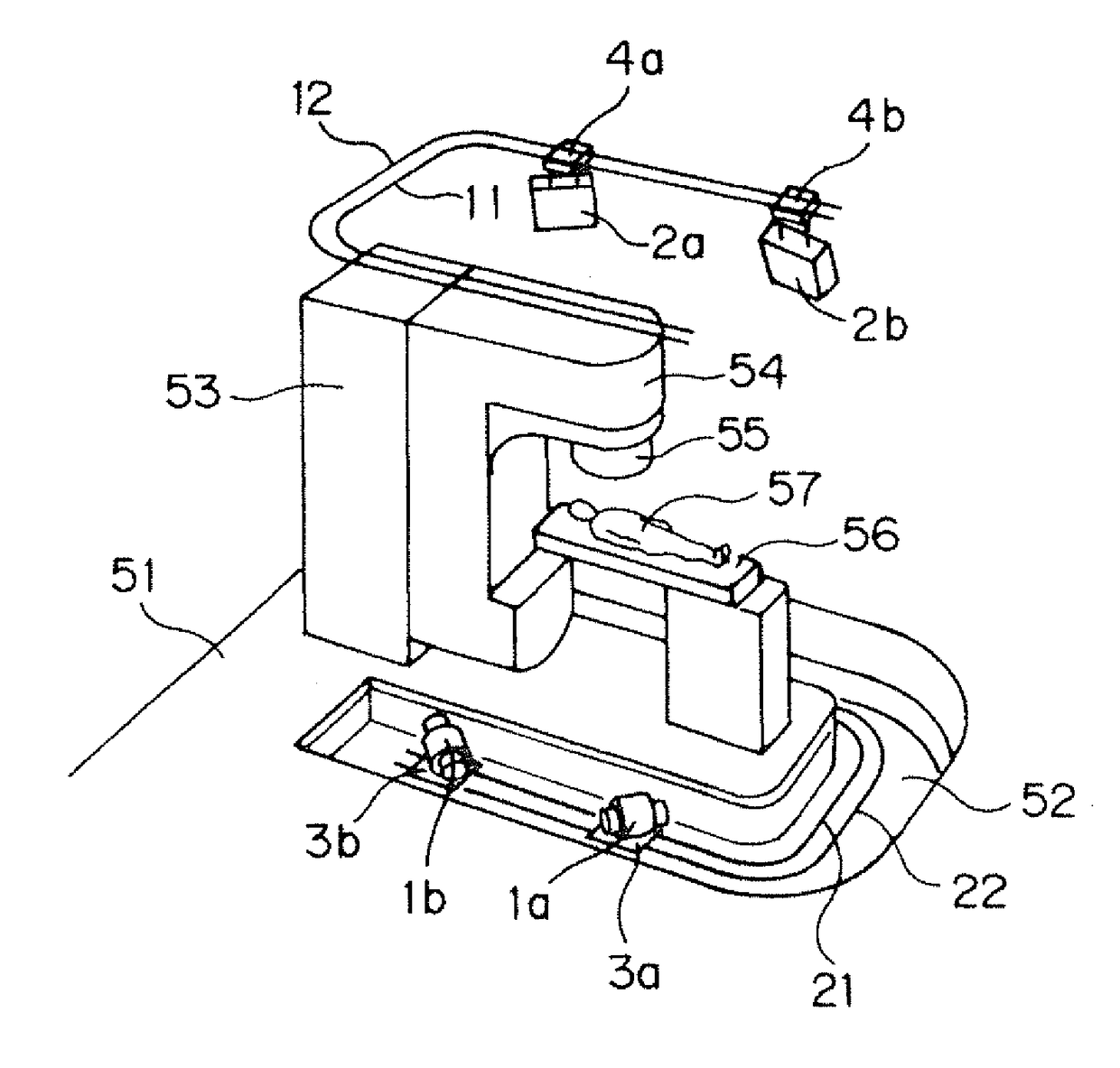
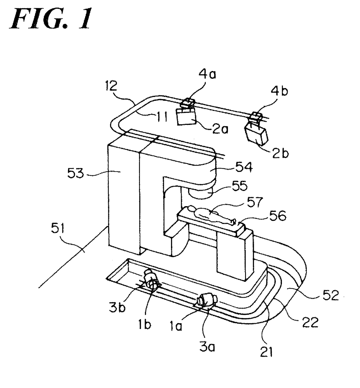
[0065]Referring to FIG. 1 and as described above, such present radiation therapeutic device is to provide an therapeutic treatment by irradiating an X-ray or an electron beam to the affected area of the subject 57 lying on the imaging table 56 and a head 55 that irradiates the therapeutic beam B to the subject 57. In addition, referring to FIG. 1 and as described above, such radiation therapeutic apparatus comprises: a first X-ray fluoroscopic mechanism consisting of the first X-ray tube 1a and the first flat panel detector 2a; and a second X-ray fluoroscopic mechanism consisting of the second X-ray tube 1b and the second flat panel detect...

embodiment 2

[0084]Next, the inventors set forth another Embodiment of the present invention. FIG. 9 is a schematic view illustrating the state in which a radiation therapy is being performed by an radiation therapeutic apparatus having an X-ray fluoroscopic device according to the aspect of the present invention. FIG. 10 is a front view illustrating a pair of X-ray irradiation region limiting members 13 arranged on the surface of the X-ray tube 1.

[0085]According to the aspect of the Embodiment 1 as described above, the pair of the filters 23, which is installed on the surface of the flat panel detector 2, allows the scattered radiation S caused by irradiation of the therapeutic beam B to the subject 57 to transmit but allows the X-ray that is irradiated from the X-ray tube 1 and transmitting the subject 57 not to transmit as the correction region forming means to form the correction region in the flat panel detector 2, in which the scattered radiation S caused by irradiation of the therapeutic ...


PUM


Abstract

An X-ray fluoroscopic device includes an X-ray imaging mechanism having an X-ray tube 1 and a flat panel detector 2; filters 23 to form a correction region, in which the scattered radiation S caused by irradiating the therapeutic beam to the subject 57 can be incident, but the X-ray that is irradiated from the X-ray tube 1 and transmits through the subject 57 cannot be incident; and a correction element that corrects the data of the region other than the correction region of the flat panel detector 2 by using the data of the correction region of the flat panel detector 2.

Description

CROSS REFERENCE TO RELATED APPLICATIONS[0001]This application relates to and claims priority from PCT Ser. No.:PCT / JP2014 / 074991 filed Sep. 22, 2014, the entire contents of which are incorporated herein by reference.FIGURE SELECTED FOR PUBLICATION[0002]FIG. 4BACKGROUND OF THE INVENTION[0003]Field of the Invention[0004]The present invention relates to an X-ray fluoroscopic device to be used relative to a radiation therapy apparatus for performing a radiation therapy by irradiating a therapy beam to a subject, a dynamic (moving) body tracking device and an X-ray detector.[0005]Description of the Related Art[0006]A radiation must be irradiated exactly to an affected region relative to the radiation therapy apparatus, having a head that irradiates the therapeutic beam and a gantry to rotate the head around a subject as the center, that performs a radiation therapy by irradiating the therapeutic beam, including e.g., X-ray and an electron beam and so forth to the affected region such as ...

Claims


Application Information

Patent Timeline
IPC IPC(8): A61N5/10A61B6/00
CPCA61N5/1077A61B6/42A61N2005/1089A61B6/487A61B6/461A61N5/1049A61N2005/1061A61B6/4007A61B6/4266A61B6/00
Inventor HIRASAWA, SHINYAARAKI, TATSUYA
Owner SHIMADZU CORP
Why Eureka
Try Eureka