Medical apparatus and method for heart valve repair

a technology for heart valves and medical devices, applied in the field of surgical devices for heart valve repair, can solve the problems of serious heart failure, difficulty in handling and implantation of very small implants used for these operations, and difficulty in temporary stabilization of tissue portions in which implants are placed, so as to achieve speed and accuracy. , the effect of improving the safety

Active Publication Date: 2017-07-20
COREMEDIC +1
View PDF8 Cites 18 Cited by
  • Summary
  • Abstract
  • Description
  • Claims
  • Application Information

AI Technical Summary

Benefits of technology

[0008]It is therefore an object of the present invention to provide an instrument for treating atrioventricular valve regurgitation of the drained human heart, which instrument overcomes disadvantages of prior art approaches and brings about advantages in terms of handling (speed and accuracy) and security for the surgeon. It is a further object to provide an improved surgical method.

Problems solved by technology

Prolapses of a leaflet of the mitral valve into the left atrium and resulting valve insufficiency can cause serious dysfunctions of the heart.
One reason for such prolapse is a damaging of the tendons (chordae tendinae) that connect the leaflets of the mitral valve to the papillary muscle through the left ventricle.
However, for the minimally invasive techniques, the temporary stabilization of the tissue portions in which implants are placed is still a challenge.
However, in open heart surgery, the handling and implantation of the very small implants used for these operations is still a challenge.
Also, according to the state of the art, the leaflet is sutured to the implanted artificial chord, this demands high skills from the surgeon and is time consuming.
Suturing of both sides (papillary muscle and leaflet) is challenging and not well defined and thus a challenge to surgeons.

Method used


Image

  • Medical apparatus and method for heart valve repair
  • Medical apparatus and method for heart valve repair
  • Medical apparatus and method for heart valve repair

Examples


Embodiment Construction

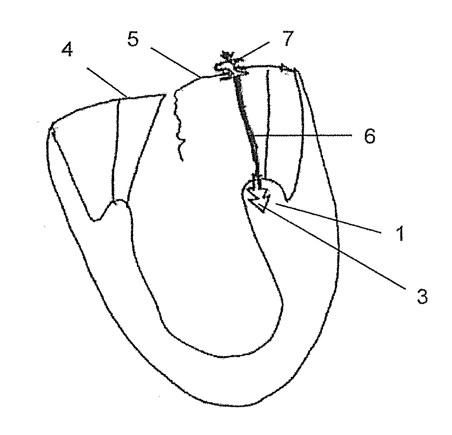
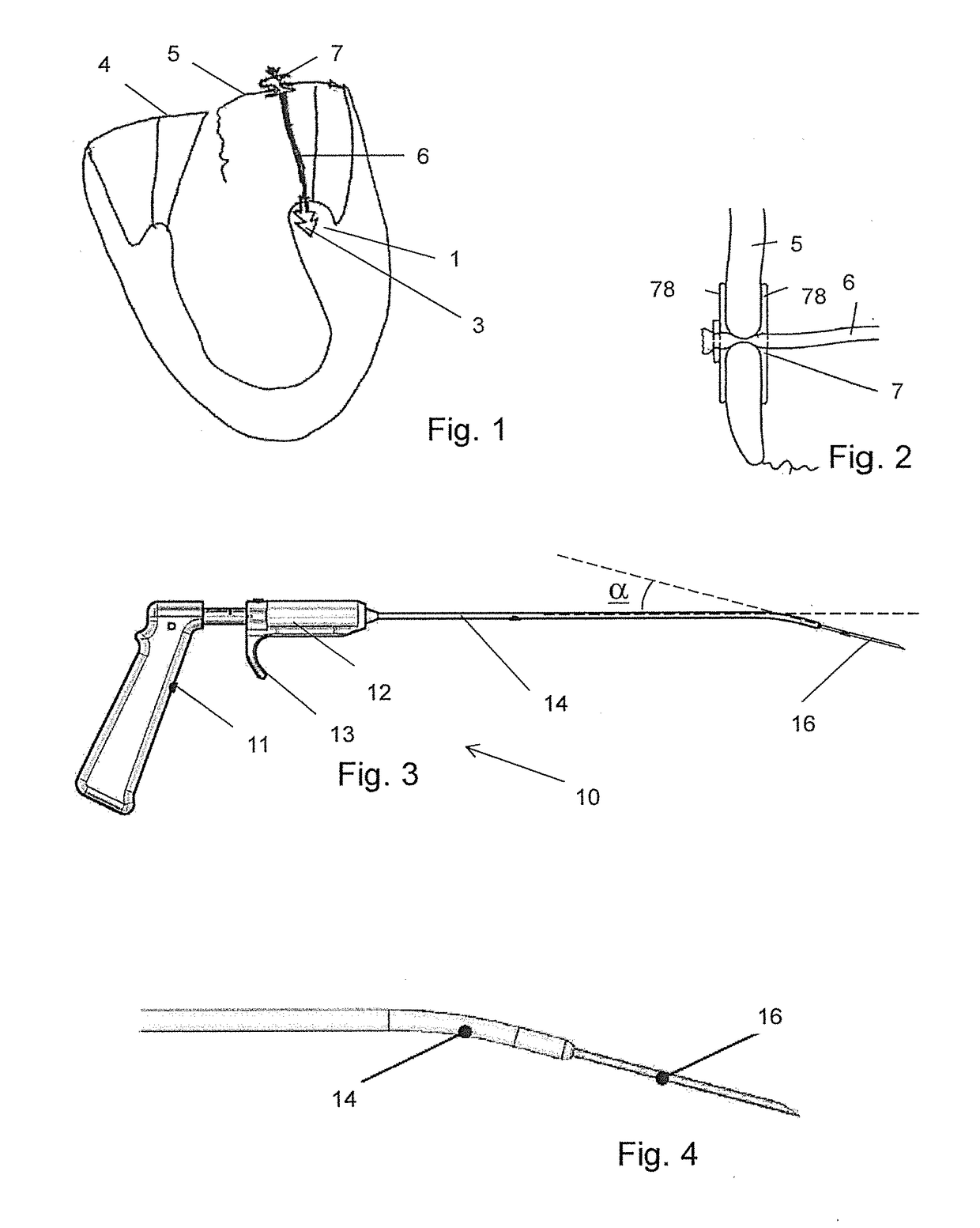
[0062]FIG. 1 shows, in part, a section through the left ventricle of the human heart with the mitral valve 4, 5. One leaflet 5 of the mitral valve has, without the surgical treatment discussed herein, the potential of prolapsing into the left atrium (not shown) because a chord for connecting the leaflet 5 to the papillary muscle 1 is damaged.

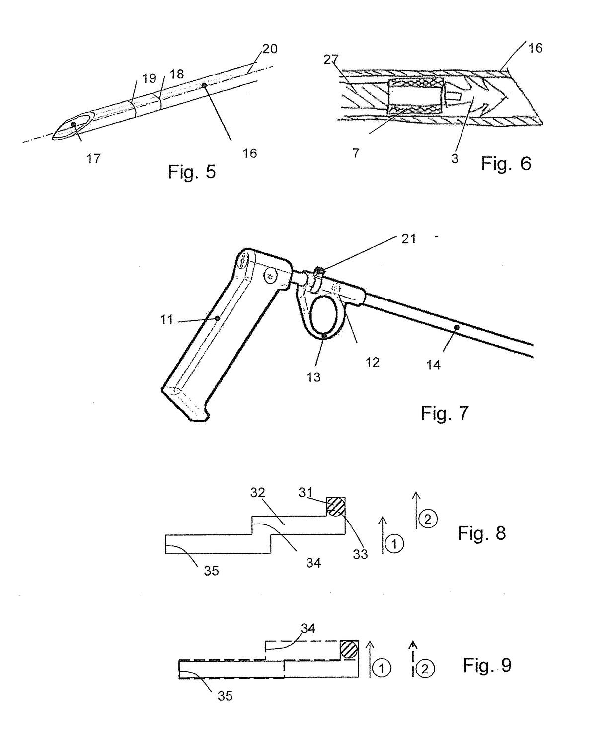
[0063]Instead of the damaged chord, in the illustrated configuration the heart is provided with an artificial chord extending between a distal implant 3 anchored in the papillary muscle and a proximal implant 7 attached to the leaflet. The distal implant may, for example, have a tip and a plurality of barbs anchoring it safely in the muscle tissue. FIG. 2 depicts the attachment of the proximal implant 7 to the leaflet in more detail. The leaflet is pierced, and the proximal implant 7 has a waist portion with two disc portions 78. The proximal implant 7 may be configured like a proximal implant of the kind described in WO 2012 / 040865 for being af...


PUM


Abstract

A surgical instrument for treating atrioventricular valve prolapse of the drained human heart, includes a handle for being held by a surgeon, a shaft extending distally from the handle, the shaft having a lumen open to a shaft distal end, a cannulated needle arranged in the shaft; with a distal end of the needle protruding from the shaft distal end at least in one possible needle position. The needle accommodates a first, distal implant equipped for being anchored in a papillary muscle, and a second, proximal implant shaped to hold on to a leaflet of an atrioventricular valve, the first and second implants each including a chord connector portion for connecting the respective implant to an artificial chord. The apparatus further includes a trigger arrangement for releasing the first, distal implant upon a first release actuation and for releasing the second, proximal implant upon a second release actuation.

Description

BACKGROUND OF THE INVENTION[0001]Field of the Invention[0002]The invention generally relates to surgical devices for heart valve repair and, more particularly, relates to an instrument for repairing an atrioventricular heart valve, in particular the mitral heart valve, in open heart surgery (surgery of the drained heart, accessed through the split sternum, via an incision or sternotomy, minithoracotomy or from another direction). The invention further relates to an instrument set and to a surgical method.[0003]Description of Related Art[0004]Prolapses of a leaflet of the mitral valve into the left atrium and resulting valve insufficiency can cause serious dysfunctions of the heart. One reason for such prolapse is a damaging of the tendons (chordae tendinae) that connect the leaflets of the mitral valve to the papillary muscle through the left ventricle. Such a damage may, for example, be a result of a myocardial infarction or as a consequence of degenerative valve disease.[0005]A re...

Claims


Application Information

Patent Timeline
Patent Type & Authority Applications(United States)
IPC IPC(8): A61F2/24A61B17/04A61B17/062A61B17/00
CPCA61F2/2457A61F2/2466A61F2/2418A61F2/2427A61B17/00234A61B2017/0464A61B17/0482A61B17/0625A61B2017/00243A61B2017/00367A61B2017/0417A61B17/0401A61B17/0469A61B17/0485A61B17/0644A61B2017/0441A61B2017/0496
Inventor SCHAFFNER, SILVIOWEIDMANN, LOUISVOGEL, ROLFGUGGISBERG, STEFANMACHLER, ANDREASVANDENBERGHE, STIJNWUTHRICH, OLIVERCARREL, THIERRYWEBER, ALBERTO
Owner COREMEDIC
Why Eureka
Try Eureka