Porous chemical mechanical polishing pads

a technology of chemical mechanical and polishing pads, which is applied in the direction of grinding devices, wrenches, manufacturing tools, etc., can solve the problems of reducing the removal rate of pads made of hard materials, forming numerous scratches, and exhibiting low removal rates

Active Publication Date: 2017-07-20
APPLIED MATERIALS INC
View PDF0 Cites 52 Cited by
  • Summary
  • Abstract
  • Description
  • Claims
  • Application Information

AI Technical Summary

Benefits of technology

[0017]In yet another implementation, a resin precursor composition is provided. The resin precursor composition comprises a first precursor formulation. The first precursor composition comprises a first resin precursor component that comprises a multifunctional acrylate oligomer, a second resin

Problems solved by technology

Polishing pads made of harder materials often exhibit high removal rates and have long useful pad life, but undesirably tend to form numerous scratches on the substrate being polished.
Polishing pads made of softer materials exhibit low scratching of substrates, but tend to exhibit lower removal rates and have shorter useful pad life.
T

Method used


Image

  • Porous chemical mechanical polishing pads
  • Porous chemical mechanical polishing pads
  • Porous chemical mechanical polishing pads

Examples


process examples

Additive Manufacturing Apparatus and Process Examples

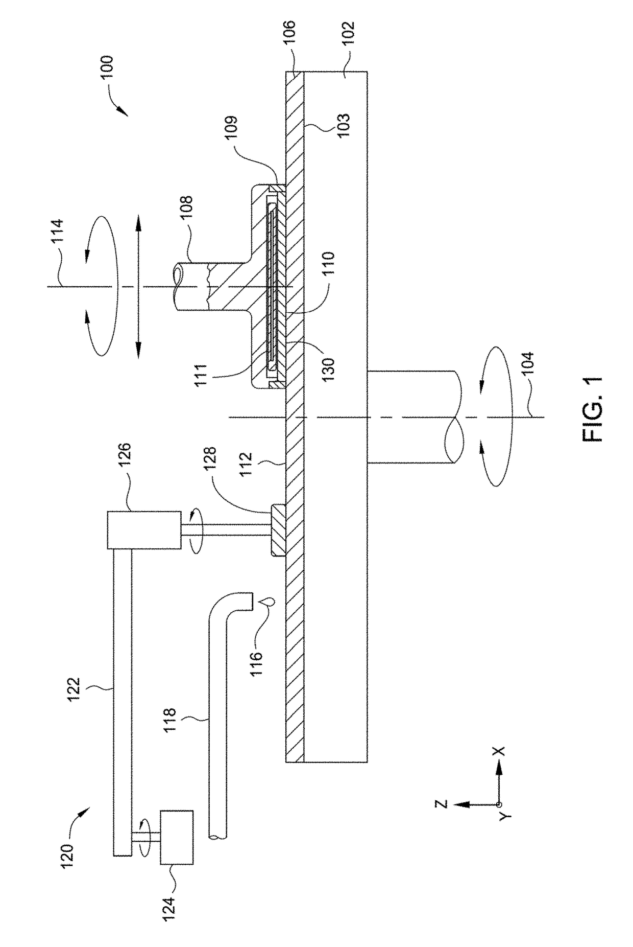
[0159]FIG. 3A is a schematic sectional view of an additive manufacturing system 350 that can be used to form a porous polishing pad using an additive manufacturing process according to one or more implementations of the present disclosure. An additive manufacturing process may include, but is not limited to a process, such as a polyjet deposition process, inkjet printing process, fused deposition modeling process, binder jetting process, powder bed fusion process, selective laser sintering process, stereolithographic process, vat photopolymerization process, digital light processing, sheet lamination process, directed energy deposition process, or other similar 3D deposition process.

[0160]The additive manufacturing system 350 generally includes a precursor delivery section 353, a precursor formulation section 354 and a deposition section 355. The precursor formulation section 354 includes a section of the additive manufacturing sy...

process example

Advance Polishing Pad Formation Process Example

[0211]In some implementations, as discussed above, the construction of the porous polishing pad 200 by an additive manufacturing process begins by creating a CAD model of the porous polishing pad design. This can be done using existing CAD design software, such as Unigraphics or other similar software. An output file, which is generated by the modelling software, is then loaded to an analysis program to ensure that the porous polishing pad design meets the design requirements (e.g., water tight, mass density). The output file is then rendered, and the 3D model is then “sliced” into a series of 2D data bitmaps, or pixel charts. As noted above, the 2D bitmaps, or pixel charts, are used to define the locations across an X and Y plane where the layers in the porous polishing pad will be built. In one implementation, the 2D bitmaps of the polishing article are represented in a data structure readable by a computer rendering device or a compu...

example 1 (

Control)

[0224]As noted in Item 1 in Table 2, a formulation that contains multifunctional oligomers with O1:O3:O4:M1 was mixed in the ratio of 30:33:15:33. Then photoinitiators and additives (P1:P2:A1 in the ratio of 67:8.25:24.75) in about 3% by weight of the formulation were added for curing. This mixture (8 g) was placed in an aluminum cup and exposed to UV radiation to cure the acrylate monomers. This did not result in measureable pores.


PUM

PropertyMeasurementUnit
Temperatureaaaaaaaaaa
Thicknessaaaaaaaaaa
Viscosityaaaaaaaaaa

Abstract

Implementations disclosed herein generally relate to polishing articles and methods for manufacturing polishing articles used in polishing processes. More specifically, implementations disclosed herein relate to porous polishing pads produced by processes that yield improved polishing pad properties and performance, including tunable performance. Additive manufacturing processes, such as three-dimensional printing processes provides the ability to make porous polishing pads with unique properties and attributes.

Description

CROSS-REFERENCE TO RELATED APPLICATIONS[0001]This application claims the benefit of U.S. provisional patent application Ser. No. 62 / 280,537, filed Jan. 19, 2016, the benefit of U.S. provisional patent application Ser. No. 62 / 331,234, filed May 3, 2016, and the benefit of U.S. provisional patent application Ser. No. 62 / 380,015, filed Aug. 26, 2016. The aforementioned related patent applications are incorporated herein by reference in their entirety.BACKGROUND[0002]Field[0003]Implementations disclosed herein generally relate to polishing articles and methods for manufacturing polishing articles used in polishing processes. More specifically, implementations disclosed herein relate to porous polishing pads produced by processes that yield improved polishing pad properties and performance, including tunable performance.[0004]Description of the Related Art[0005]Chemical mechanical polishing (CMP) is a conventional process used in many different industries to planarize surfaces of substra...

Claims


Application Information

Patent Timeline
IPC IPC(8): B24B37/22B33Y80/00B33Y10/00B24B37/24B24B37/26
CPCB24B37/22B24B37/24B33Y80/00B33Y10/00B24B37/26C08J9/142B24B3/28B24D18/0045C08J9/149C08J9/06B24D3/22B24D3/18
Inventor GANAPATHIAPPAN, SIVAPACKIAPATIBANDLA, NAG B.BAJAJ, RAJEEVREDFIELD, DANIELREDEKER, FRED C.ORILALL, MAHENDRA C.FU, BOYIYAMAMURA, MAYU
Owner APPLIED MATERIALS INC
Why Eureka
Try Eureka