Peak frequency detection device, method, and program

Inactive Publication Date: 2017-07-20
SFFT CO LTD
View PDF0 Cites 0 Cited by
  • Summary
  • Abstract
  • Description
  • Claims
  • Application Information

AI Technical Summary

Benefits of technology

The patent describes a method for detecting a peak frequency in a digital data string. By using a multiplier and a digital band pass filter, the method can extract the signal in a specific frequency band without the need for an analog filter. The method can also be used with a single frequency component or multiple frequency components. The use of a smaller multiplier can reduce the number of excessive frequency components and make it easier to exclude them using the digital band pass filter. The technical effects of the patent are improved accuracy and efficiency in detecting peak frequencies in digital data.

Problems solved by technology

However, increase in the number of FFT application causes a problem of a longer period for cutting out a signal wave to be subject to FFT in proportion to the number of cutting out times.
The literature includes no recognition of a potential problem that it is difficult to avoid a negative influence by disturbance noise with an input signal wave having a short time length, and thus neither suggests nor teaches any solution to such a potential problem.
In this case, it may be difficult to specify the peak frequency.
Although various efforts have been made in order to avoid the constraint of the conflicting relationship upon obtaining a peak frequency of an input signal, there has not yet been found any universal solution.

Method used


Image

  • Peak frequency detection device, method, and program
  • Peak frequency detection device, method, and program
  • Peak frequency detection device, method, and program

Examples


first embodiment

1. First Embodiment

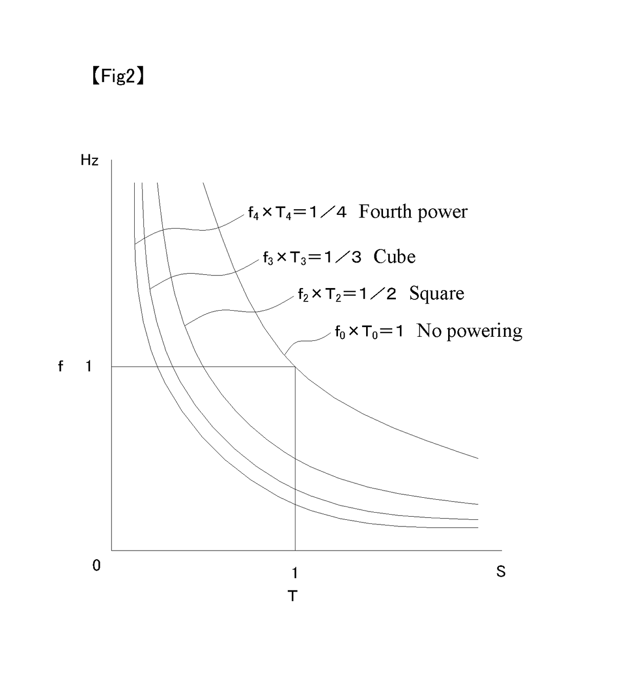
[0066]Described in a first embodiment are a peak frequency detection device and a Doppler measuring instrument including the same. The peak frequency detection device is configured to detect a peak frequency f in a frequency band from fcl to fch determined by a lower limit value fcl and an upper limit value fch of a received digital data string sampled at a sampling frequency fs while satisfying a desired frequency resolution ftg and a desired time window length Ttg.

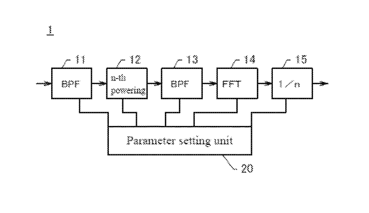
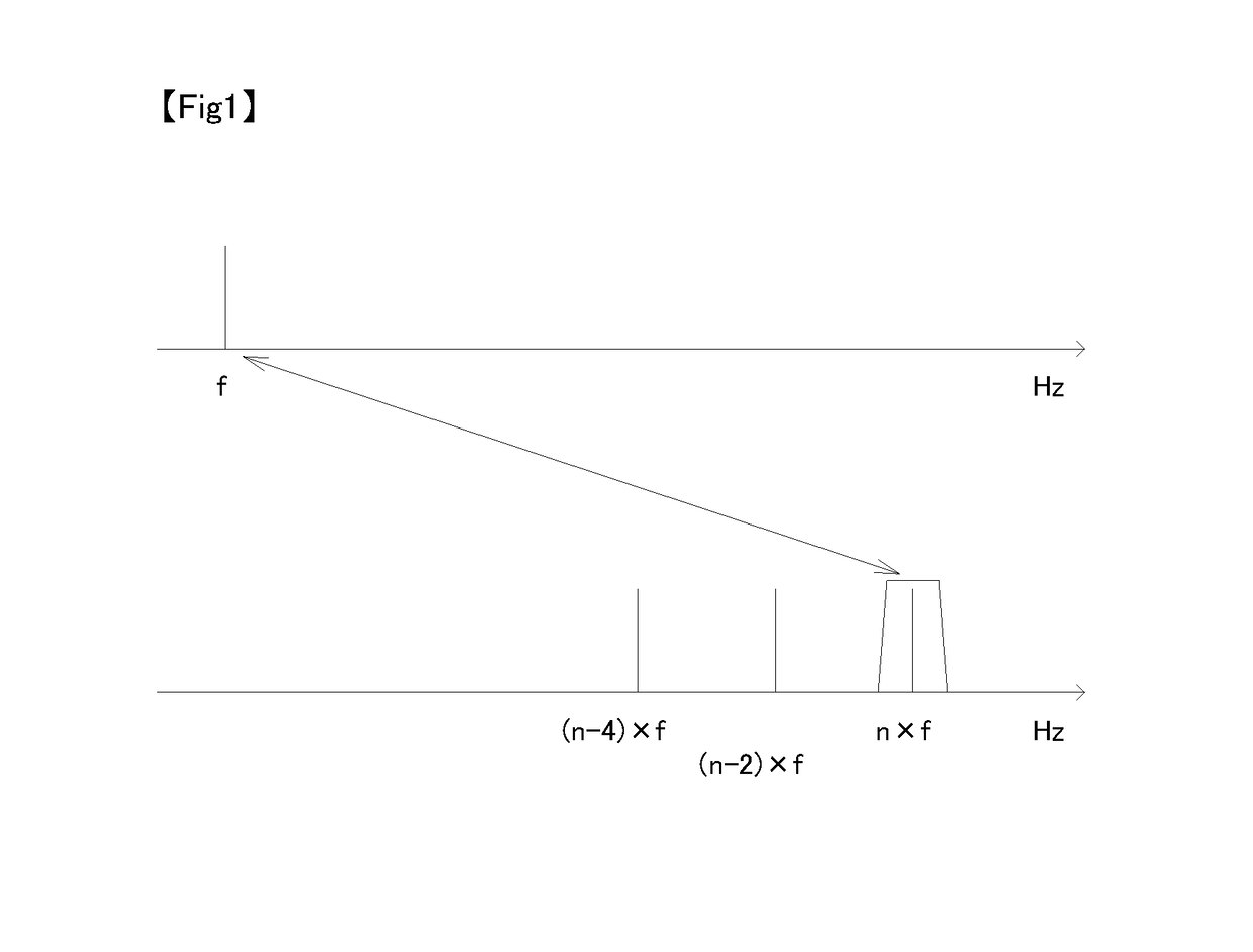
[0067]As depicted in FIG. 3, a peak frequency detection device 1 according to the first embodiment of the present invention includes a first digital band pass filter (BPF) unit 11, an n-th powering unit 12, a second digital band pass filter (BPF) unit 13, an FFT unit 14, and a 1 / n multiplication unit 15.

[0068]Initially described is a procedure of determining a multiplier n, an FFT sampling frequency fs applied in a frequency analysis, and an FFT sampling number N applied in the frequency analysis.

[0069...

second embodiment

2. Second Embodiment

[0114]FIG. 8 is a block diagram depicting a configuration of a peak frequency detection device 3 according to a second embodiment of the present invention. The peak frequency detection device 3 additionally includes a decimation unit 16 provided ahead of the first digital BPF 11 in the peak frequency detection device 1. The decimation unit 16 is provided for decreasing the sampling frequency by decimating an A / D converted digital data string to decrease. In a case where the sampling frequency fs of a digital data string input to the peak frequency detection device 3 is high and the multiplier n and a cutoff frequency fch of the first digital BPF 11 satisfy the relationship fs>4×n×fch, the second embodiment is preferably applicable.

[0115]The decimation unit 16 decimates the digital data string to 1 / r (r is an integer of 2 or more) and causes the decimated digital data string to satisfy the following relationship.

fs>2×n×fch

In this expression, fs denotes a sampling...

third embodiment

3. Third Embodiment

[0124]FIG. 9 is a block diagram depicting a configuration of a peak frequency detection device 4 according to a third embodiment of the present invention. The peak frequency detection device 4 additionally includes a decimation unit 17 subsequently to the second digital BPF 13 according to the first embodiment. The first digital BPF unit 11, the n-th powering unit 12, and the second digital BPF 13 operate similarly with input digital data having the sampling frequency fis replacing the sampling frequency fs of the first embodiment. In a case where the sampling frequency fs of a received digital data string is high and the multiplier n and the cutoff frequency fch of the first digital BPF 11 satisfy the relationship fs>4×n×fch, it is typically preferred to apply the second embodiment for a fewer calculation amount. Meanwhile, the present embodiment also achieves processing satisfying the desired time window length ftg and the desired time window length Ttg.

[0125]Th...


PUM


Abstract

A peak frequency detection device provided with: an n multiplication unit that multiplies each element of a digital data string by n (n is an integer of 2 or more); an FFT unit that derives, as a virtual peak frequency, a frequency that corresponds to the maximum value of a power spectrum that is obtained by performing a fast Fourier transform of a digital data string of N (N is an integer of a power of 2 and is determined in accordance with a sampling frequency (fs), a sampling resolution (ftg), and a time window length (Ttg)) sample frequencies (fs) that are multiplied by n; and a 1 / n multiplication unit that outputs the value of the virtual peak frequency multiplied by 1 / n as the peak frequency of the digital data string. The peak frequency detection device satisfies n≧1 / (ftg×Ttg), fs / (n×ftg)≦N≦fs×Ttg, and fs>2×n×fch.

Description

TECHNICAL FIELD[0001]The present invention relates to a device, a method, and a program configured to detect a peak frequency having a maximum power spectrum.BACKGROUND ART[0002]Assuming that, in fast Fourier transform (FFT), T0(s) denotes a time window length, fs(Hz) denotes a sampling frequency, and N (N is an integer of a power of 2) denotes a sampling number, the following relationship is established.T0=N / fs   [Formula 1]The time window length has a reciprocal f0(Hz) called a frequency resolution, and satisfies the following relationship.f0=1 / T0   [Formula 2][0003]When a signal wave is frequency-analyzed by means of FFT, a time window length corresponds to a time length of the signal wave to be subject to FFT, a frequency resolution corresponds to a minimum resolution of the frequency of the signal wave, i.e. frequency detection accuracy. Hereinafter, this time window length will also be referred to as “period for cutting out a signal wave to be subject to FFT”, “a period of a s...

Claims


Application Information

Patent Timeline
IPC IPC(8): G01R19/04
CPCG01R19/04G01S7/526G01S15/50G10G7/02G10L25/90G01R23/16G01R23/167G01R23/177G06F17/141G01S7/356G01R23/00
Inventor AKUTSU, KAZUSHI
Owner SFFT CO LTD
Why Eureka
Try Eureka